Engineering Review
Mobile Perimeter Security Engineering
Anatomy of the Frontier BP-4A-3500 Rapid Deployment Perimeter Security System.
When Permanent Infrastructure Isn’t an Option
A conventional perimeter security system begins with design work, followed by site preparation, cable installation, regulatory approvals, and commissioning. The entire process typically takes anywhere from several weeks to several months. For a facility expected to remain in service for years, this is a perfectly reasonable investment.
However, some deployment scenarios share a very different set of constraints: the asset is valuable, but its presence at a given location lasts only a matter of days.
- military equipment and other assets deployed during training exercises, field maneuvers, tactical operations, or reconnaissance missions;
- rail, aircraft, and road vehicles parked at temporary staging locations;
- temporary sites and facilities established for a specific operation;
- personnel and assets during official state visits;
- agricultural machinery left in the field overnight.
What these scenarios have in common is not the industry they belong to, but the risk profile they share. The assets are valuable, the deployment window is short, and permanent infrastructure is either impractical or economically unjustifiable.
In practice, this leaves only two options. The first is to assign security personnel or conduct regular patrols. The second is to accept the risk and do nothing.
Both approaches carry hidden costs that rarely appear in the project budget. A security post does not scale: one person can physically monitor only a single sector, and at night that sector is limited by available lighting or the range of the observation equipment. Patrols inevitably create gaps between inspection cycles. Maintaining round-the-clock security over several days requires shift rotations, transportation, food, and accommodation. In practice, the cost of “simply assigning personnel” to secure a 200 × 200 m site for three days can be comparable to that of a technical solution—while providing less consistent and ultimately less effective coverage.
System Overview
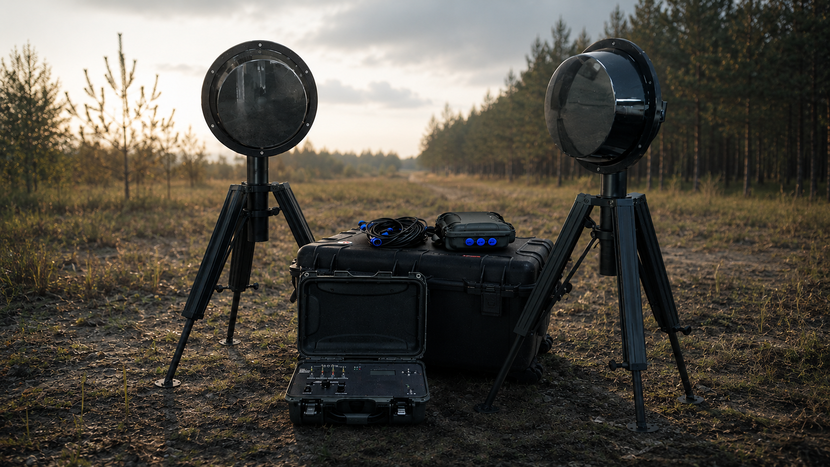
The Frontier BP-4A-3500 is a rapid-deployment microwave perimeter security system developed by the Ukrainian company FortiSec in collaboration with the Italian manufacturer of bistatic microwave intrusion sensors, CIAS. The system is built around CIAS ERMO 482X PRO microwave barrier sensors, which serve as its primary detection technology.
The system is designed to secure enclosed sites with side lengths of up to 200 m, delivering up to 800 m of perimeter coverage and protecting approximately 4 hectares.
The system is supplied in five transport cases:
-
Component
Transport case
CaseL, 762 × 533 × 457 mm, 42 kg
Qty.4
Contents
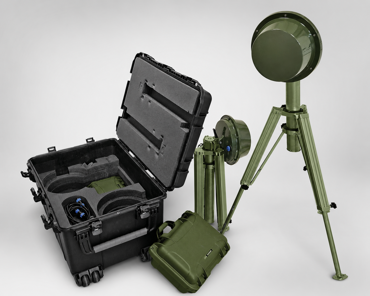
One pair of microwave barrier nodes (transmitter and receiver) mounted on tripods, one S-size case containing the power supply and battery, cable kit, documentation
-
Component
Wireless control unit
CaseM, 391 × 307 × 173 mm, 3 kg
Qty.1
Contents
Control panel, display, audible/visual alarm, radio module, power supply with battery
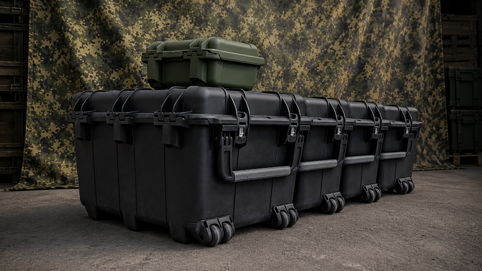
The complete system weighs 171 kg and is distributed across five transport cases. Deployment requires transportation and a minimum two-person team, making the system suitable for vehicle-supported operations rather than backpack-portable use. In return, it requires no foundations, no trenching or cable installation, and no external power source.
The specified deployment time is up to 20 minutes. The system provides up to 72 hours of autonomous operation, with extended endurance available as an optional configuration.
Perimeter Configuration: Why This Design?
The system’s most interesting engineering decision isn’t found in the specification sheet, but in the way the perimeter is laid out.
Four bistatic microwave barriers form four independent detection zones, one along each side of the protected site. Each barrier consists of two physically separated nodes: a transmitter (TX) and a receiver (RX). Rather than powering each barrier independently, the system pairs like nodes for power distribution. A single power supply serves either the TX nodes of two adjacent barriers or the corresponding RX nodes.
This arrangement places two like nodes at every corner of the perimeter: either a pair of transmitters (TX) or a pair of receivers (RX). Transmitter and receiver nodes are never mixed at the same corner.
At first glance, this may appear to be a cable management decision. In reality, it serves a much more fundamental purpose. A bistatic barrier operates by transmitting microwave energy from the transmitter toward the receiver. If the transmitter of one barrier were placed next to the receiver of an adjacent barrier, it would radiate directly toward that neighboring receiver. The result would be unwanted signal coupling, requiring mitigation through frequency separation, changes to the deployment geometry, or reduced receiver sensitivity.
The “like nodes at every corner” layout eliminates the problem at the architectural level rather than relying on configuration or tuning. Each transmitter is directed only toward its corresponding receiver on the opposite corner of the perimeter, preventing direct coupling into neighboring receivers by design.
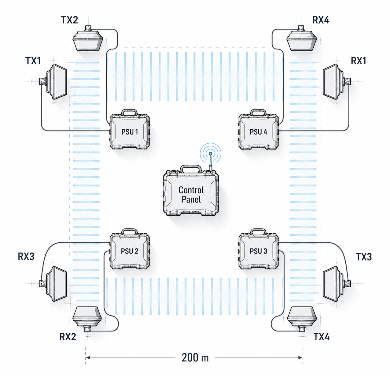
An important consequence of this layout is that four power supplies are both necessary and sufficient. Two serve the transmit side, and two serve the receive side. The architecture achieves the minimum component count—not through simplification for its own sake, but as a direct result of the system’s functional requirements.
Configuration
The practical implication for deployment planning is that the system is designed around a closed four-section perimeter and is not intended for arbitrary configurations. It is not designed to protect an 800 m straight-line perimeter or sites with highly irregular boundaries. Instead, the deployment area must be suitable for a closed four-sided perimeter.
What Does the Barrier Detect?
A bistatic microwave barrier establishes an invisible electromagnetic field between the transmitter and the receiver. Rather than forming a narrow beam, it creates a three-dimensional detection volume. The behavior of the sensor is governed by the geometry of this detection volume rather than by a single line of propagation.
The system operates in the X-band (9.46–10.58 GHz), with an effective isotropic radiated power (EIRP) ranging from 25 to 500 mW. Sixteen independently selectable modulation channels, controlled by an onboard microprocessor, provide the flexibility required to prevent mutual interference between adjacent barriers.
A key capability for rapid-deployment applications is the barrier’s ability to detect an intruder regardless of how the perimeter is crossed—whether upright, bent over, crawling, or rolling. The specified target velocity range is 0 to 15 m/s.
The lower limit is equally significant. A specified minimum target velocity of zero indicates that the barrier does not lose detection when an intruder enters the detection zone and then remains stationary. This is a non-trivial capability for sensors based on signal-change detection, where simpler implementations may no longer detect a target once motion ceases.
How the Barrier Decides to Trigger an Alarm
The barrier’s onboard microprocessor employs fuzzy-logic algorithms, referred to as Fuzzy Behavior Models. Rather than making a simple threshold comparison, the system evaluates multiple characteristics of the received signal—including target size, signal shape, and the rate at which the signal changes—and compares the resulting signature against a library of predefined behavioral patterns.
In other words, the decision logic is concerned not simply with whether the signal has changed, but with whether the observed signal pattern is consistent with human intrusion.
This represents a fundamental departure from conventional threshold-based detection. Rather than relying solely on signal amplitude, the system evaluates the overall characteristics of the received signal. As a result, events that may produce similar signal levels—such as animals, wind-driven vegetation, or rain—can be distinguished from human intrusion based on their signal signatures rather than on threshold crossings alone.
The specified performance figures are a probability of detection (Pd) of 0.99 and a false alarm rate (FAR) of one alarm per year. In the specification, both values are explicitly qualified as being subject to the signal-to-noise ratio (SNR), an important detail rather than fine print. It means that the stated performance is tied to the radio environment at the installation site. This is not a disclaimer but an acknowledgement of a fundamental limitation: no sensor can guarantee a given false alarm rate regardless of the electromagnetic conditions in which it operates.
Built-in Self-Diagnostics
In addition to detecting intruders, the barrier continuously monitors its own operational integrity. By dynamically tracking the absolute received signal level established during commissioning, it can detect degradation of the microwave components as well as attempts to mask or tamper with the sensor. Environmental conditions are monitored in parallel.
Every alarm event and significant signal change is recorded in the barrier’s RAM with a date and time stamp. This information is invaluable during incident analysis, allowing investigators to determine not only whether an alarm occurred, but also what triggered it.
System outputs are divided into three categories: Alarm, Tamper, and Fault. By distinguishing between intrusion events, equipment tampering, and technical faults, the system enables operators to respond appropriately to each condition.
Factory Calibration as an Engineering Design Choice
The system is supplied as a plug-and-play solution. The sensing subsystem is factory-calibrated for the specific system configuration, with no provision for field adjustment. This simplifies deployment by eliminating both sensor tuning and the need for specialized personnel training.
This design choice merits closer examination because it reflects a deliberate engineering trade-off.
In a permanent installation, a microwave barrier of this class typically offers an extensive set of configuration options, including sensitivity thresholds, modulation channel selection, and signal-processing parameters. A qualified engineer adjusts these settings to suit the specific deployment environment, taking into account factors such as terrain, vegetation, and nearby metal structures. This approach can deliver optimal performance, but it also requires specialist expertise, dedicated configuration software, and time on site.
In a rapid-deployment system, this flexibility becomes a trade-off. The person deploying the system is typically not the engineer who designed it, but whoever is available on site—often working at night, under time pressure, and in challenging conditions. The more field configuration the system requires, the greater the likelihood of deployment errors and inconsistent performance.
FortiSec deliberately chose the opposite design philosophy. Rather than relying on field configuration, the sensing subsystem is factory-calibrated for the standard 4 × 200 m perimeter layout. The system arrives ready for deployment, with no sensor adjustment required on site.
The practical benefits are straightforward: the system can be deployed without a specialist, without configuration software, and without the risk of field configuration errors. Equally important, factory calibration provides consistent, repeatable performance across different deployment teams and installation sites.
The practical implication is that the deployment site must fit the system configuration—not the other way around.
This is not a limitation to be corrected but a deliberate engineering trade-off. Understanding that trade-off during system selection helps ensure that the system is applied in the scenarios for which it was designed.
Engineering Design: What Makes the Sensor Portable
The ERMO 482X PRO barrier was not originally designed as a portable device. The portability of the Frontier system is achieved through a series of engineering decisions, each eliminating one of the infrastructure dependencies typically associated with permanent perimeter installations.
Wireless Communications Instead of a Wired Bus. Each barrier node incorporates an integrated LoRa transceiver and antenna, eliminating the need for a wired communications link between the microwave barriers and the control unit. This is arguably the single most significant design decision enabling rapid deployment, as cable installation is typically the most time-consuming aspect of deploying a conventional perimeter security system. The radio link operates in the 868 MHz band using 100 mW LoRa modems with a receiver sensitivity of up to −144 dBm.
Tripods Instead of Foundations. Unlike many other perimeter detection technologies, bistatic microwave barriers do not require precise mutual alignment of the transmitter and receiver. Reliable operation depends primarily on maintaining stable positioning at the installation site. To eliminate the need for permanent mounting structures, the manufacturer developed a dedicated tripod featuring pan and tilt adjustment, height adjustment, and a built-in mechanism for compensating uneven ground. The tripod legs are additionally secured with ground stakes to ensure stability. Constructed from aluminum, each tripod weighs 7 kg. The complete system includes eight tripods, one for each barrier node.
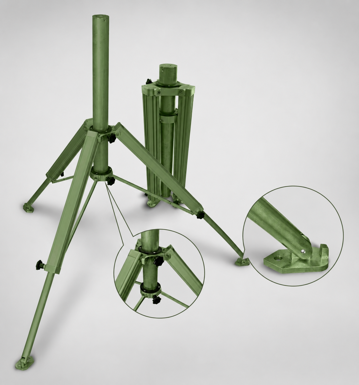
The ability to operate without precision alignment is fundamental to the system’s rapid-deployment concept. Any technology requiring optical alignment over a 200 m path would inevitably extend deployment time well beyond the specified 20-minute window.
LiFePO₄ Batteries Instead of External Power. Lithium iron phosphate (LiFePO₄) batteries were selected not simply for their energy capacity, but for their operational characteristics. Their flat discharge curve provides a stable supply voltage throughout the discharge cycle, allowing the sensors to operate consistently from a fully charged battery to near depletion. Their inherent thermal and chemical stability reduces the risks associated with transportation and storage. Equally important for field deployment in Ukraine, they retain reliable capacity at temperatures down to −30 °C, making year-round autonomous operation practical.
Transport Cases Instead of Equipment Cabinets. All system components are transported and stored in dedicated protective cases, eliminating the need for permanent equipment cabinets. The cases feature NK7-rated impact-resistant construction with rubber reinforcement, an IP67 ingress protection rating, an automatic pressure equalization valve, and a three-stage latching system. The larger L-size cases are equipped with polycarbonate wheels with polyurethane treads mounted on stainless-steel bearings, allowing the complete system to be transported over uneven terrain.
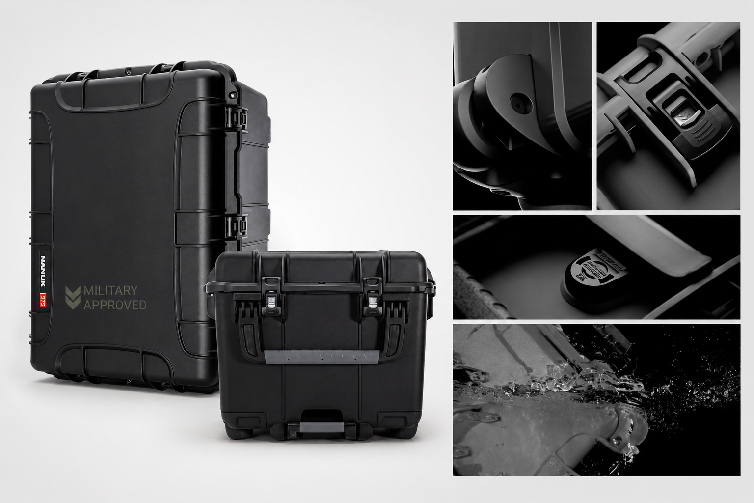
The integrated wheels are intended for transport over paved and other hard surfaces. On soft ground, sand, or snow, the 42 kg transport case must be carried manually. This is not a design deficiency but an inherent consequence of deploying a ruggedized transport case in off-road conditions, and should be considered when planning field logistics.
Industrial Connectors Instead of Field Wiring. The barrier nodes are connected to the power units using 5 m patch cables fitted with factory-installed threaded circular connectors. The connectors feature gold-plated copper contacts, an IP68 ingress protection rating, and an operating temperature range of −40 to +85 °C. No cable glands, field crimping, or soldering are required during deployment.
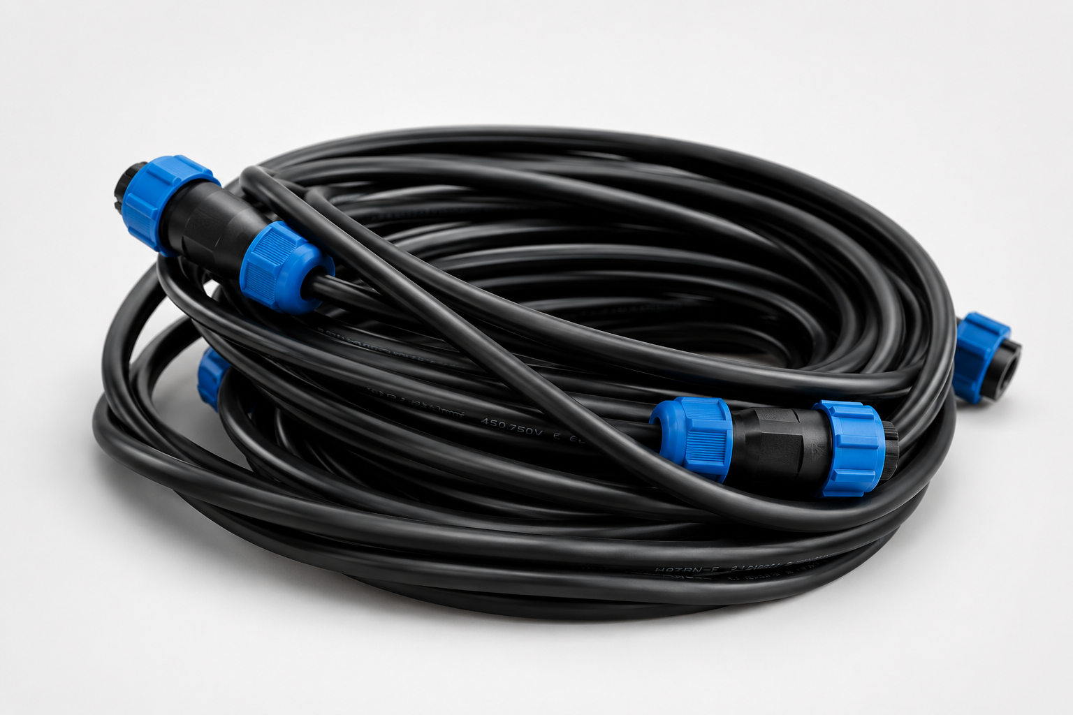
The barrier nodes themselves provide IP66 ingress protection and IK10 impact resistance, with an operating temperature range of −35 to +65 °C.
Power System: Validating the Specified Operating Autonomy
Each pair of barrier nodes is powered by a dedicated 20 Ah LiFePO₄ battery pack operating at a nominal voltage of 18 V, providing an energy capacity of 360 Wh. The wireless control unit is powered independently by a 12 Ah, 18 V LiFePO₄ battery pack with an energy capacity of 216 Wh.
Assuming the specified operating autonomy of 72 hours (three days), the average continuous power budget is:
-
Component
Barrier node pair power unit
Available Energy360 Wh
Average Continuous Power (72 h)
5.0 W per node pair (2.5 W per node)
-
Component
Wireless control unit
Available Energy216 Wh
Average Continuous Power (72 h)
3.0 W
The calculated values are consistent with the expected power consumption of a microwave barrier in this class, including a reasonable margin for operation at sub-zero temperatures and wireless communications. The specified operating autonomy of up to three days therefore appears to be a conservative engineering estimate rather than a marketing-driven figure.
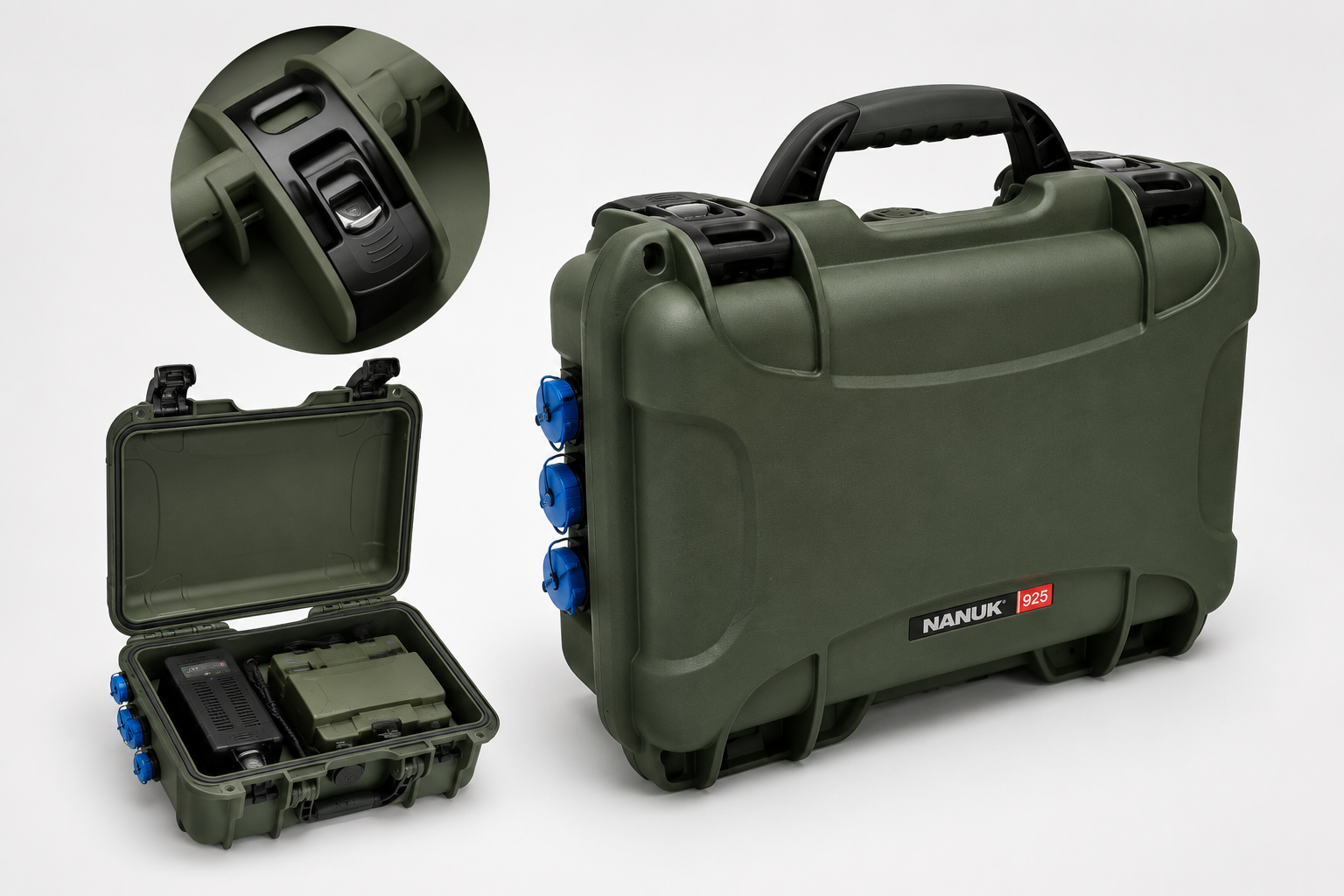
The batteries can be recharged either from a 230 V AC mains supply or from 12–48 V AC or DC low-voltage power sources. For field deployment, the latter capability is considerably more important, as the system can be recharged directly from a vehicle’s electrical system. This eliminates dependence on grid power at the deployment site and enables a self-contained operational cycle: deploy, operate, recover, and recharge while in transit.
Charging at sub-zero temperatures should be confirmed with the supplier, as permissible charging conditions for lithium-based battery chemistries vary with temperature and may influence winter operating procedures.
Radio Link Security and Operator Safety
The specified communication range between the barrier nodes and the wireless control unit is up to 1,000 m under line-of-sight conditions and up to 500 m in obstructed environments, including wooded areas and buildings. The effective operating range can be extended through the use of external antennas.
The wireless control unit supports three operating modes, selected using a rotary switch: stand-alone, remote terminal, and master. The latter two modes require a second wireless control unit connected via a wired communications link, allowing the operator station to be positioned up to 1,000 m from the protected perimeter.
The purpose of these operating modes is practical rather than architectural: they allow the operator station to be relocated away from the protected perimeter. For most civilian applications, this capability provides little operational benefit. In the first deployment scenarios listed earlier, however, maintaining a stand-off distance between the operator and the protected site can be a significant operational advantage.
A dedicated radio silence mode is also provided and is protected against inadvertent activation. In this mode, the wireless control unit no longer polls the barrier nodes periodically but instead remains in a passive listening state, receiving only alarm transmissions initiated by the sensors.
Radio silence mode represents a deliberate operational trade-off. It reduces the system’s RF signature by eliminating routine polling transmissions from the wireless control unit.
The appropriate operating mode therefore depends on whether minimizing RF emissions or maintaining continuous system health monitoring is the higher operational priority.
Another characteristic that should be stated explicitly is that the system is an active sensing system. Its operation depends on continuous RF emissions in two frequency bands: the X-band microwave field that forms the detection zone and the 868 MHz communications channel linking the barrier nodes to the wireless control unit. This is an inherent consequence of the system architecture, not a design flaw. The trade-off is that the system is not intended for covert operation. Where electromagnetic detectability is an operational consideration, deployment should be planned accordingly.
Operator Interface
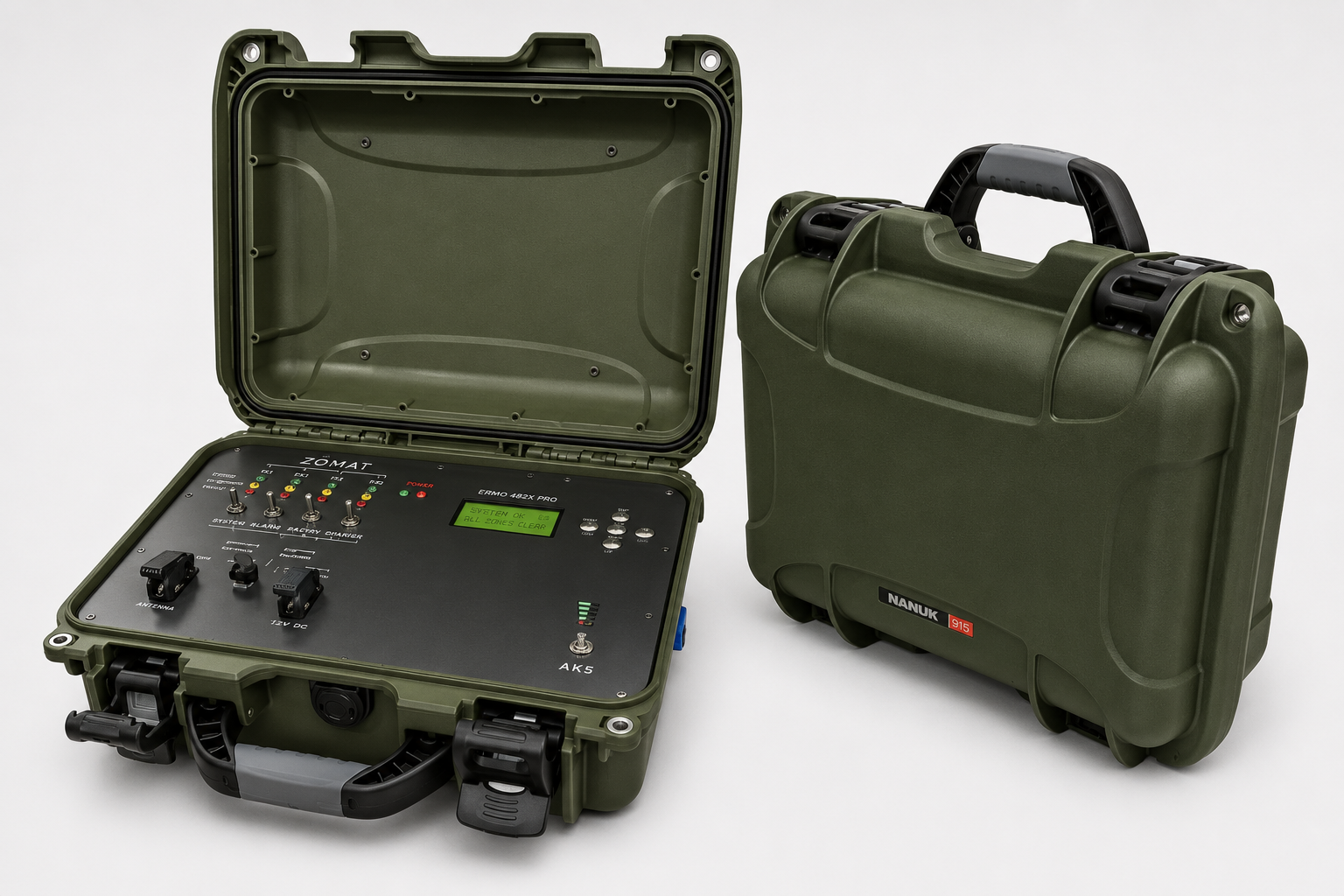
The wireless control unit is designed around an intuitive operator interface requiring minimal training. The front panel includes:
- Four independent switches for arming and disarming the four protected zones.
- Guarded switches for enabling radio silence mode and disabling the built-in audible alarm, protected against inadvertent operation.
- A rotary mode selector for choosing the operating mode.
- A battery status test button with a multi-level LED indicator that also displays charging progress.
- An information display with navigation keys.
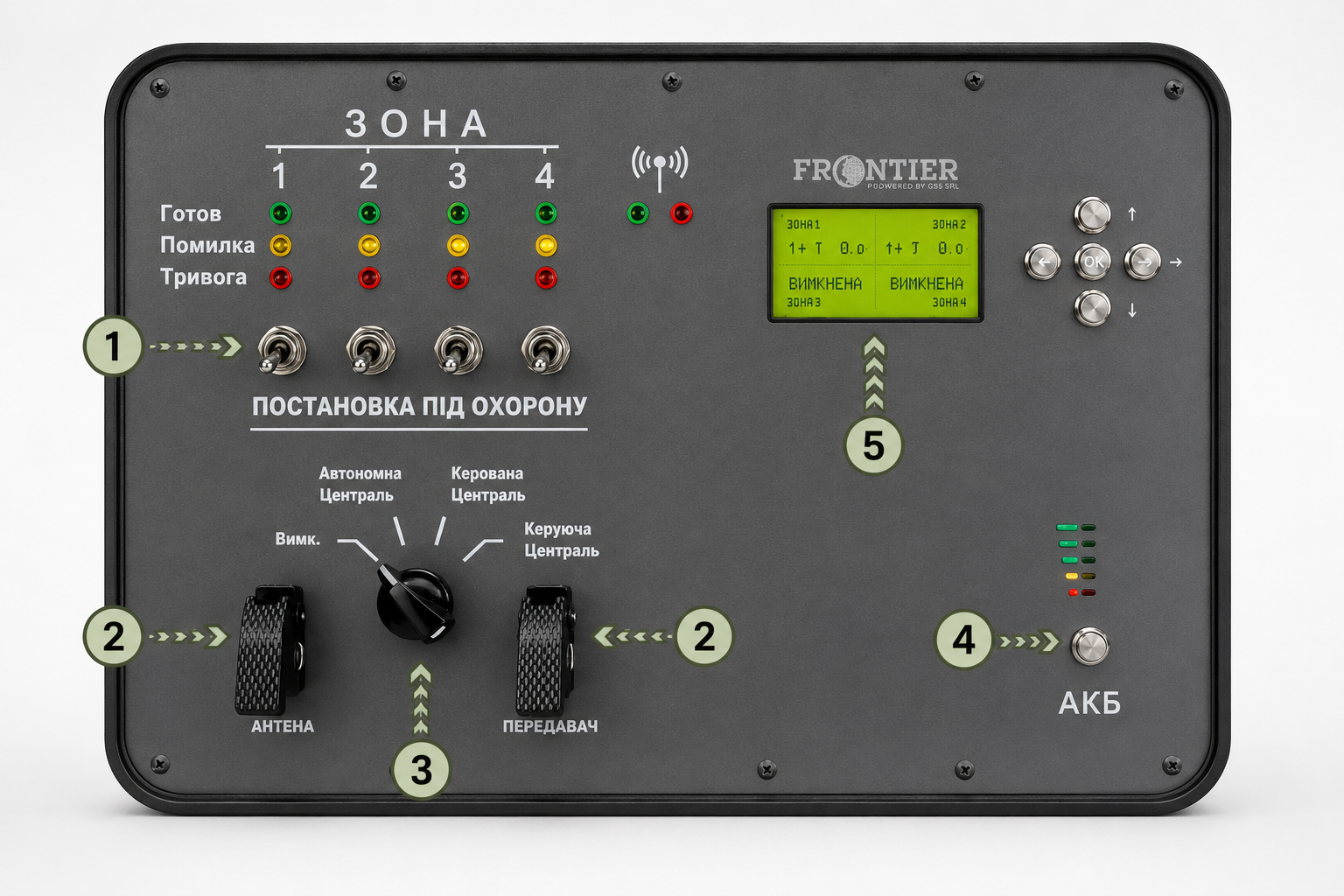
LED indicators provide the status of each protected zone, showing Ready, Fault, or Alarm. Additional indicators show radio transmission and reception activity, while a high-output built-in audible alarm provides immediate local notification of alarm events.
The information available on the display deserves particular attention. It is considerably more comprehensive than is typical for a portable system:
-
Displayed Parameter
Operational Significance
-
Zone status: Disarmed / Armed / Alarm
Basic perimeter status monitoring
-
Data radio link status
Confirms communication with the corresponding barrier node
-
Radio transmit/receive activity
Confirms active packet exchange
-
Barrier node battery charge level
Indicates the remaining operating autonomy of the node
-
Received signal strength and signal-to-noise ratio (SNR)
Provides early indication of link degradation before communication failure
-
Internal barrier node temperature
Monitors environmental conditions affecting electronic components
-
Event type: Alarm / Tamper / Fault
Enables differentiated operator response
-
Hardware/firmware version
Identifies the installed configuration during maintenance and service
The last two parameters in the second group are particularly valuable. Displaying both the battery charge level and the received signal quality for each barrier node allows the operator to identify gradual degradation before it develops into a communication failure or loss of detection capability.
This is an important engineering characteristic. Rather than simply indicating that a fault has occurred, the system provides advance warning of developing problems, allowing maintenance or battery replacement to be planned before protection is compromised.
System Limitations
The system is designed to detect unauthorized perimeter crossings. It is not intended to provide a response capability. Any deployment therefore requires an appropriate response plan, including personnel, communications, and procedures, to ensure that intrusion alarms can be acted upon effectively.
-
The spatial resolution of alarm reporting is one protected zone.
In the standard four-sector configuration protecting an 800 m perimeter, an alarm can be localized only to the affected 200 m sector. The system therefore indicates which sector has been breached, but not the precise location of the crossing within that sector.
-
The system does not provide visual alarm verification.
It includes no integrated means of confirming the cause of an alarm visually. Each alarm therefore requires either dispatching a response team or verifying the affected sector using a separate surveillance system.
This has important operational implications. To realize the full value of the detection system, it should ideally be complemented by a surveillance capability—such as a thermal imaging camera or a visible-light camera with illumination—aligned with the same four protected sectors. This allows alarms to be verified rapidly before personnel are dispatched.
-
The system is not designed for centralized monitoring.
Operator access remains local to the protected site. Although the control unit may be relocated by up to 1,000 m using a wired link in master/remote terminal mode, the system cannot be integrated into a centralized security operations center.
This reflects its intended role: protecting temporary or remote sites with a dedicated local operator rather than forming part of a larger, centrally managed security infrastructure.
-
Large animals.
Because the system is optimized for detecting human intruders, sites where large animals are routinely present should be validated under actual operating conditions before the system is relied upon for unattended overnight protection.
-
Fixed deployment geometry.
The standard system architecture assumes a closed quadrilateral perimeter with sides of up to 200 m. Perimeters that differ substantially in shape or dimensions should be evaluated individually to determine whether the required detection coverage can be achieved.
-
Logistics.
The complete system weighs approximately 171 kg and is distributed across five transport cases. Deployment therefore requires suitable transportation and is most efficiently carried out by a two-person team.
Appropriate Applications and Deployment Limits
Suitability
Well suited
-
Temporary parking area for vehicles or equipment on an open, level site
The site geometry matches the standard four-sector deployment, with minimal environmental clutter within the detection zones.
-
Perimeter protection during military exercises or field operations
Autonomous battery operation, vehicle charging capability, and the ability to relocate the operator station make the system well suited for temporary field deployments.
-
Temporary security for official events or outdoor venues
Rapid deployment and recovery without permanent infrastructure or ground disturbance.
Suitability
Suitable with site validation
-
Overnight protection of agricultural machinery in open fields
An intended application, but local conditions—including the presence of large animals and ground characteristics—should be evaluated before unattended operation.
-
Protection of rail vehicles during temporary storage
Suitability depends on whether a closed four-sided perimeter can be established around the protected assets.
Suitability
Generally unsuitable
-
Sites containing dense vegetation or buildings within the protected perimeter
The volumetric detection fields require reasonably clear protected zones, and radio communication range may be reduced in obstructed environments.
-
Irregularly shaped sites or linear perimeters
The system architecture is optimized for a closed four-sector perimeter rather than arbitrary or elongated layouts.
-
Applications requiring precise intrusion localization
Alarm reporting is limited to the protected sector (approximately 200 m in the standard configuration) rather than the exact point of intrusion.
Pre-Purchase Checklist
Questions worth answering before the purchase, not after:
- What is the typical geometry of my sites — do they fit within a closed quadrilateral with sides of up to 200 m?
- Do these sites offer vehicle access to the deployment points?
- How many people make up the deployment team, and who exactly trains them?
- How will I verify an alarm — which surveillance capabilities will operate alongside the system?
- Who physically receives the alarm, and where are they located? Is a second control unit required?
- What is the charging procedure at sub-zero temperatures?
- Is operating autonomy beyond three days required — and for exactly how long?
- Which deployment scenarios require radio silence mode, and who makes the decision to activate it?
The Role of the Engineering Partner
Unlike permanent perimeter security systems, the Frontier BP-4A-3500 does not require a conventional installation project. That is, in fact, the purpose of its design. Rapid deployment replaces permanent infrastructure.
What it does require is a sound engineering assessment of whether a particular site is compatible with the system’s fixed deployment geometry, and what complementary capabilities—such as surveillance and response—are needed to convert intrusion detection into an effective security solution.
FortiSec’s role is to ensure that the system is applied within its intended design envelope. This includes assessing representative customer sites, confirming compatibility with the standard deployment geometry, recommending complementary alarm verification measures, and preparing deployment procedures for the operating team.
This assessment is most valuable before a purchasing decision is made. Its deliverable is not a conventional design specification, but a validated deployment concept: a clear definition of where the system fits, how it should be deployed, and which complementary capabilities are needed to turn intrusion detection into an effective operational response.
The technical brochure provides complete system specifications, recommended deployment layouts, and detailed technical characteristics of every subsystem.
Download the Frontier BP-4A-3500 Brochure
Next step. Tell us about your site or deployment scenario. FortiSec engineers will assess the site geometry, determine whether it is compatible with the Frontier system’s standard deployment architecture, and prepare a practical deployment concept tailored to your application. This includes the recommended barrier layout, power configuration, communications architecture, and deployment plan.
A single engineering consultation is typically enough to determine whether the system is a good fit—and, if it is, how it should be deployed.