Engineering overview
Long-Range Surveillance: Where VMS Ends and C2 Begins
An engineering analysis of the HELIOS C2 platform and its role in security system architecture.
When a system specification includes a requirement such as “detect an intruder at a range of 5 kilometers,” most design decisions immediately focus on selecting the right camera. That is a natural starting point—but the wrong one.
Choosing a camera with the appropriate optics is the easiest part of the problem. The real engineering challenge begins afterward: how to cue the camera to the target, how to confirm the detection, which coordinate system should be used to record the target’s location, and ultimately, which platform is responsible for video archiving, operator account management, and cybersecurity.
This article explains why long-range surveillance does not fit within the architecture of a conventional video management system (VMS), what architectural layer takes its place, and where the boundaries of that layer lie.
Using the Tanz Security HELIOS C2 platform as a practical example, we examine what this layer is designed to do, what the manufacturer documents, and which capabilities and performance characteristics must be validated during system design and deployment.
This article is based on the manufacturer’s official documentation. Wherever a specification depends on the system configuration or requires on-site validation, this is explicitly noted.
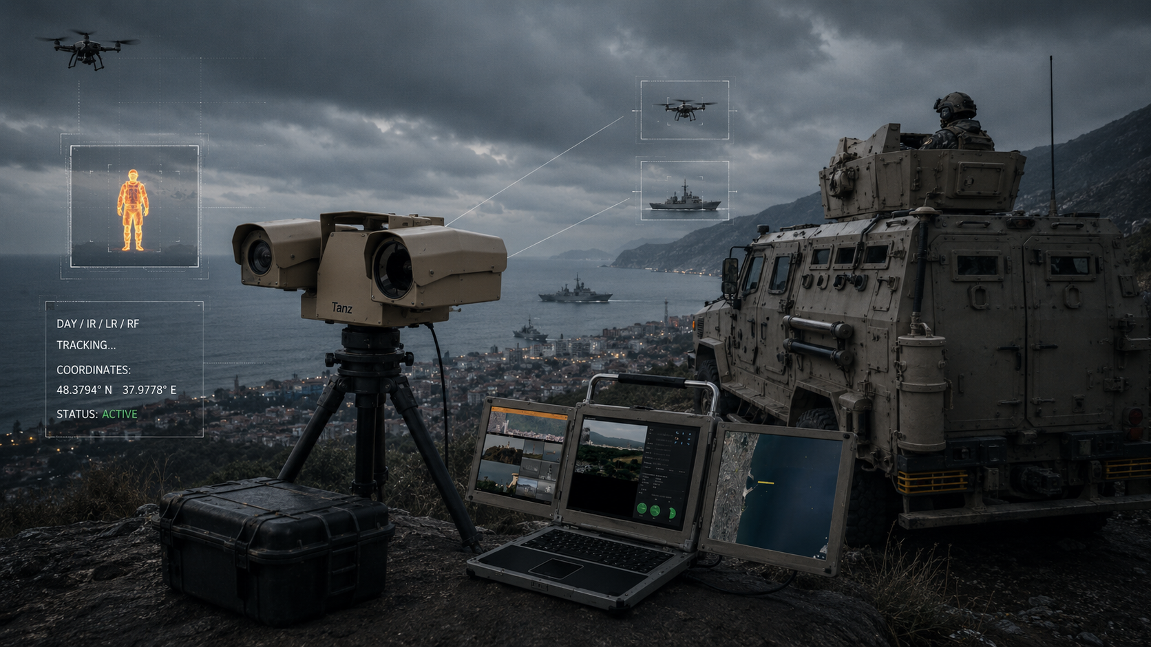
Part 1. A Problem That Cannot Be Solved at the Camera Level
It All Starts with Geometry
The camera’s field of view is determined by the image sensor size and the lens focal length:
HFOV = 2 · arctg( w / 2f )
where w is the horizontal sensor dimension, and f is the lens focal length.
Consider, for example, a visible-light channel with a 1/1.8-inch image sensor, approximately 7.2 mm wide, and a 750 mm lens at the telephoto end of its zoom range. This is a representative long-range channel configuration, not a specification of any particular model.
HFOV = 2 · arctg(7,2 / 1500) ≈ 0,55°
This leads to two consequences that shape everything else.
First implication. Covering a full 360° horizon with a channel like this requires approximately 654 viewing positions. If the platform spends just two seconds slewing, settling, and capturing an image at each position, a complete scan takes more than twenty minutes.
This is not a limitation of the pan-tilt mechanism—it is a consequence of geometry.
Second implication. At a distance of 5 km, the visible-light channel covers a strip only about 48 meters wide. A 640 × 512 thermal imaging channel with a 12 µm pixel pitch and a 225 mm lens provides a field of view of approximately 1.96°, corresponding to 171 meters at the same distance.
Both figures are negligible compared to the area that must be monitored.
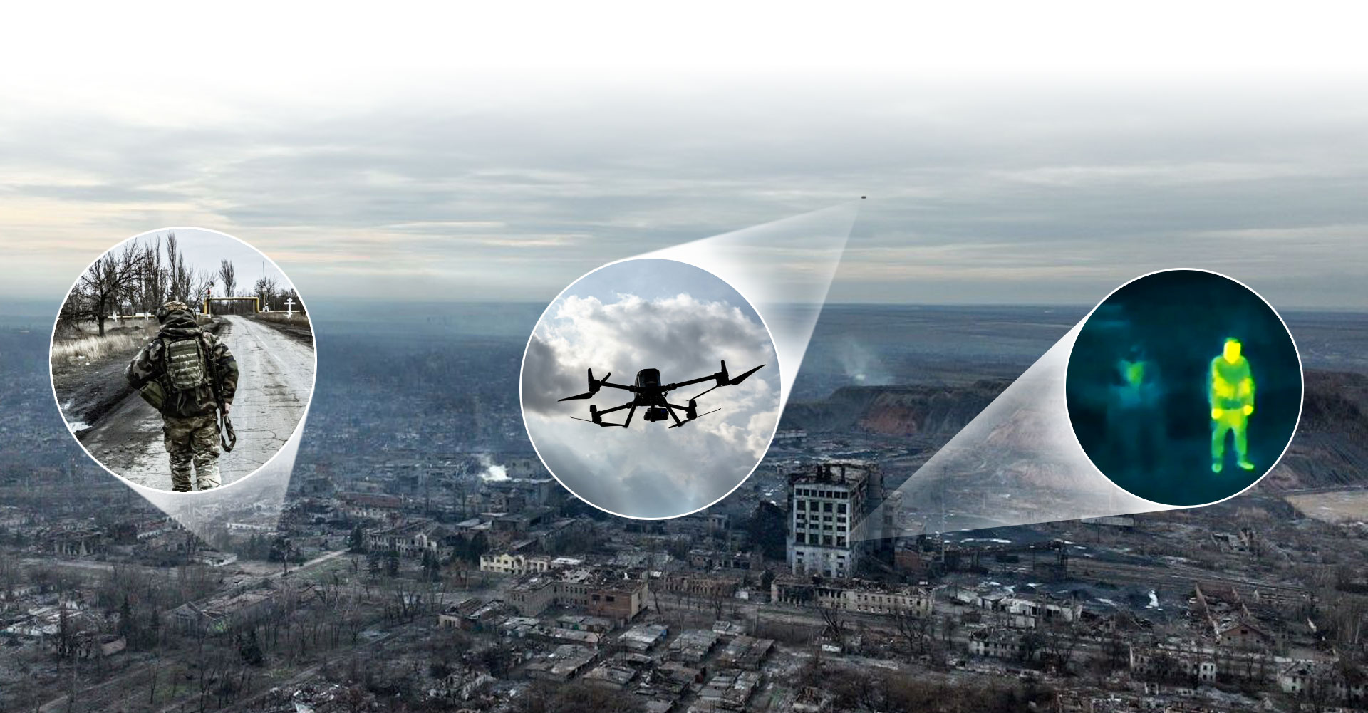
How Many Pixels Does a Target Need?
The classical Johnson criteria relate the number of resolution elements across a target’s critical dimension to the level of discrimination an operator can achieve. Expressed in pixels, the approximate thresholds for a 50% probability of success are:
Consider a human target with a characteristic dimension of 0.75 m and the same thermal imaging channel. The instantaneous field of view (IFOV) of a single pixel is approximately 53 µrad.
Detection
2
pixels across the target’s critical dimension
Estimated range ≈ 7.0 km
Recognition
8
pixels across the target’s critical dimension
Estimated range ≈ 1.8 km
Identification
12.8
pixels across the target’s critical dimension
Estimated range ≈ 1.1 km
The gap between detection and identification exceeds a factor of six. This is the fundamental reason why long-range surveillance systems rely on a multi-sensor architecture.
The sensor used for detection and the sensor used for identification are physically different sensors, even when they are integrated into the same pan-tilt platform.
For the visible-light channel used in the example above, the calculated ranges appear almost unrealistic: 75 km for detection and 11 km for identification. This serves as a useful reality check.
At these distances, the limiting factor is no longer the optics—it is the atmosphere. Atmospheric transmission, target contrast, and above all, turbulence in the near-ground boundary layer degrade image quality regardless of the optical system.
Any quoted detection range that does not specify the atmospheric conditions should be treated as a theoretical geometric limit, not an operational performance specification.
Why the Conventional VMS Model Breaks Down
A video management system (VMS) is built on the assumption that each camera continuously observes a fixed scene, while the operator or video analytics interpret whatever appears within its field of view. The archive exists so that events can be reviewed after they occur.
A long-range surveillance system operates on the opposite principle. For most of the time, its sensor is not looking where the event occurs. Recording “everything” is meaningless because “everything” is just one narrow sector out of hundreds. In most cases, reviewing the event afterward is impossible because, at the time it occurred, the camera was pointed somewhere else.
The primary objective, therefore, is not recording—it is timely sensor cueing. Everything else is designed to support that objective.
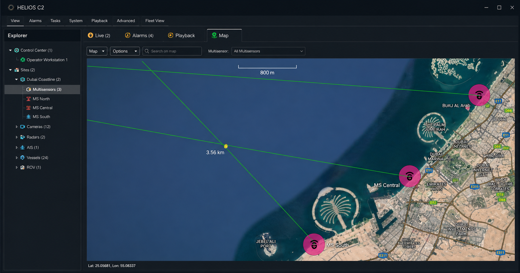
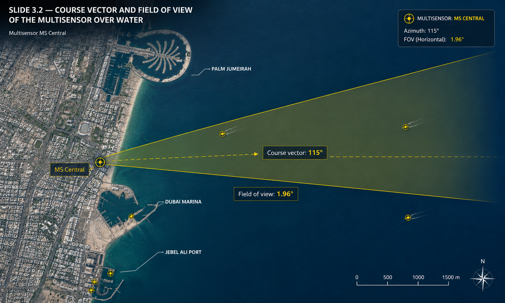
The second illustration is worth examining closely. The yellow sector represents the sensor’s actual optical field of view overlaid on the map. It clearly shows how little area the sensor covers at any given moment—and why precise cueing is so critical.
What a Panorama Really Is
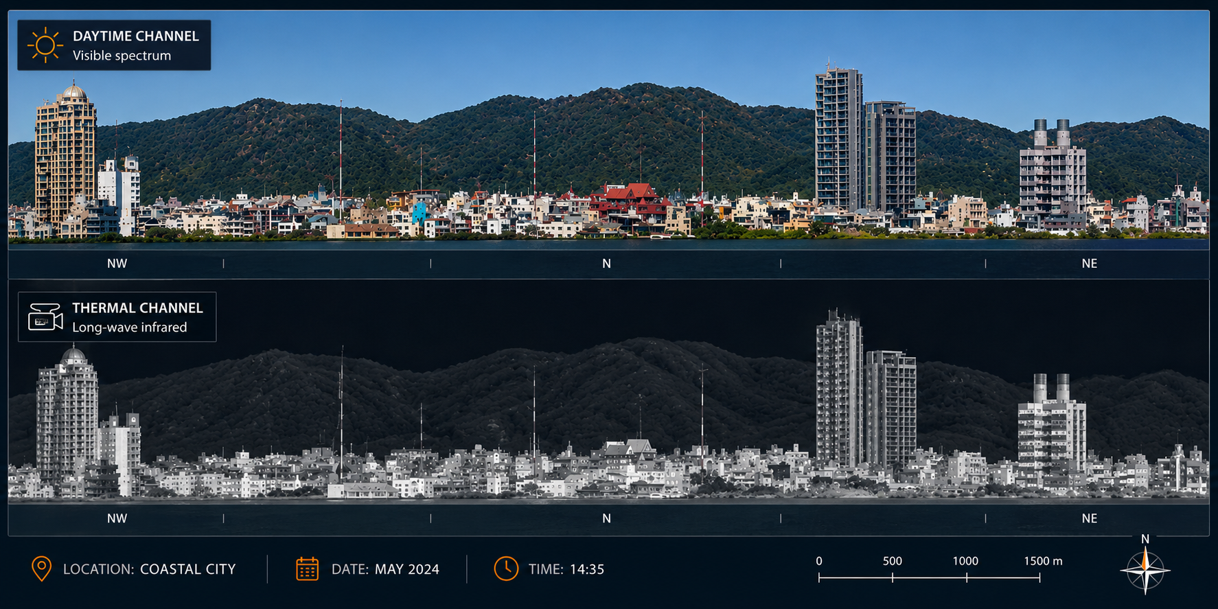
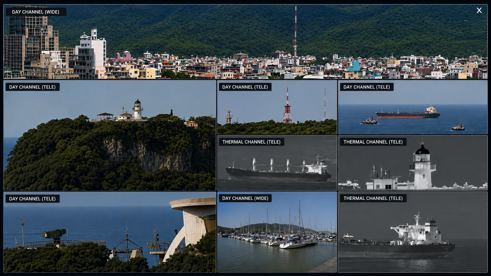
HELIOS automatically generates a panoramic view of the horizon by capturing a sequence of images at successive azimuth positions. Panoramic views are available for both the visible-light and thermal imaging channels.
Confirmed fact
The panoramic view is constructed from a sequence of images captured one after another.
Engineering interpretation
This means that the panoramic view is a reference image of the terrain, not a representation of the current situation. Each section reflects the scene at the moment that particular image was captured.
The time required to generate a complete panoramic view is equal to the number of azimuth positions multiplied by the time needed for the platform to slew, settle, and capture each image.
Practical conclusion
The panoramic view solves the orientation problem: it allows the operator to understand where the sensor is pointed and what lies along that azimuth. It does not solve the detection problem. It should not be relied upon as the primary means of monitoring the surveillance area.
Part 2. The Target Cueing Chain
If a long-range optical channel cannot search, something else must tell it where to look. That is the role of the command-and-control layer. Let’s break that process down into its individual stages.
Detection source → Target cueing → Sensor slewing → Target tracking → Identification → Geolocation → Decision
Each stage introduces its own uncertainty, and those uncertainties accumulate throughout the chain.
Detection source
Ground and maritime radars, AIS receivers, buried sensors, satellite navigation, underwater acoustics or the platform’s own video analytics. What they share is wide-area coverage; what they cost is azimuth accuracy, from fractions of a degree to several degrees.
Target cueing and sensor slewing
The cue is taken by the wide-field thermal imaging channel and handed off to the narrow-field channel only after acquisition. Accuracy here is set by platform mechanics and alignment, not by software.
Track management
Target ID, range, heading, speed and UTM coordinates. Three different coordinate systems, and every transition between them requires the precisely known position and heading of the device involved.
Identification and classification
Neural network–based detection with twelve predefined object classes. A single universal classification accuracy figure does not exist.
Geolocation
The digital compass provides direction, the laser rangefinder provides range. Without the rangefinder, the calculated coordinates are approximate.
Image management
Haze reduction, atmospheric turbulence compensation, stabilization, range measurement, and monitoring of the computing module’s utilization.
Stage 1. Detection Source
HELIOS accepts inputs from ground and maritime radars, Automatic Identification System (AIS) receivers, buried sensors, Global Navigation Satellite Systems (GNSS), underwater acoustic sensors, as well as its own video analytics.
What these sources have in common is their wide-area coverage: each can detect a target in areas where the long-range optical channel is not looking.
The key parameter is azimuth accuracy. The azimuth accuracy of a surveillance radar depends on its class and typically ranges from fractions of a degree to several degrees.
Now compare that with the 0.55° field of view of the visible-light channel from Part 1.
The conclusion is uncomfortable, but unavoidable: target cueing from a radar with a one-degree azimuth error does not guarantee that the target will appear within the narrow field of view. At a distance of 5 km, an angular error of one degree corresponds to 87 meters of lateral offset. The target may fall completely outside the sensor’s field of view.
This is precisely why a multi-sensor payload makes sense as a single integrated system. The initial cue is acquired by the wide-field thermal imaging channel, where the target is reliably brought into view. Once the target has been acquired, it is handed off to the narrow-field visible-light channel for identification.
A multi-sensor payload is not simply a collection of cameras in a common enclosure—it is a two-stage sensor cueing architecture.
Stage 2. Target Cueing and Sensor Slewing
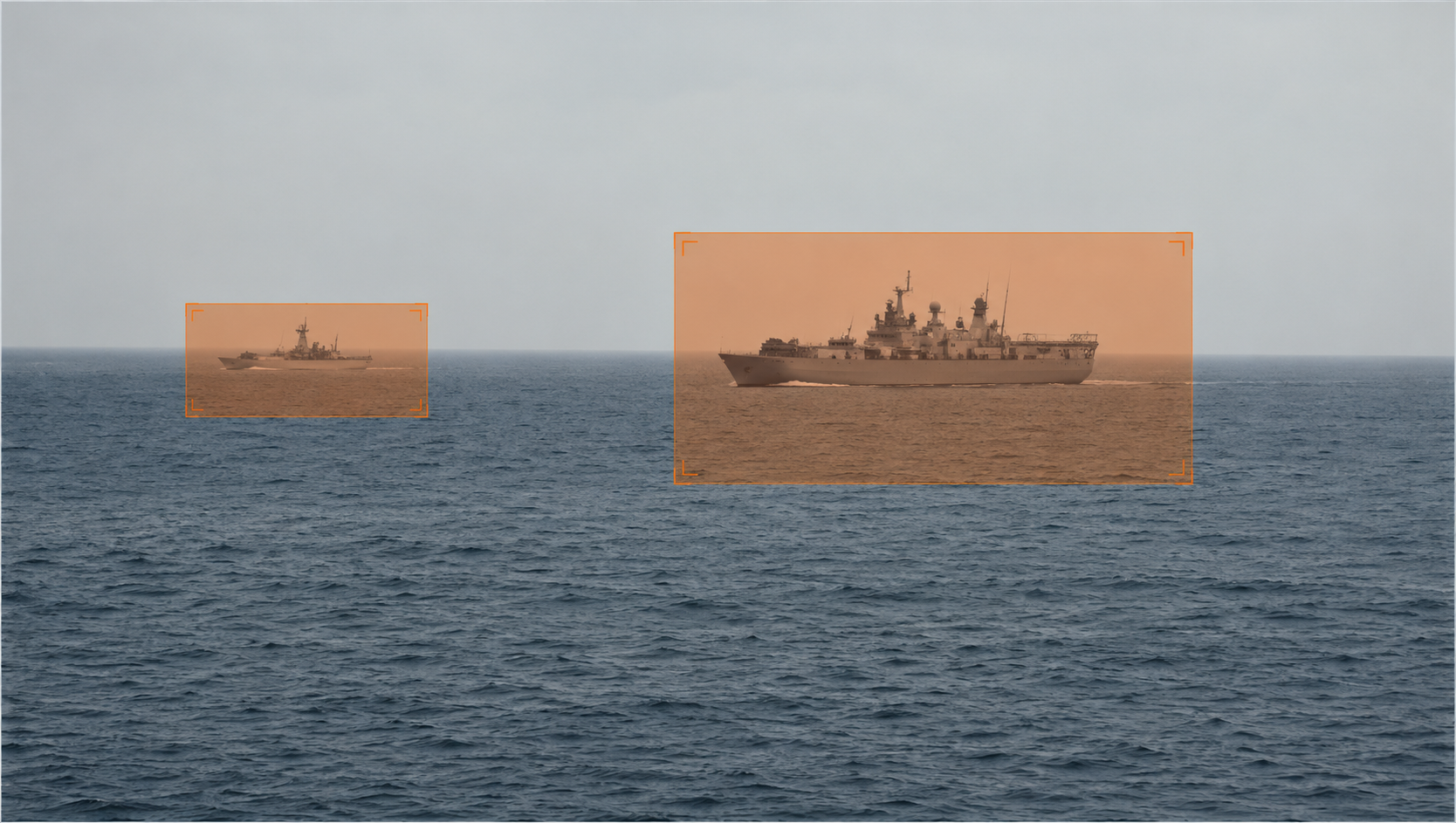
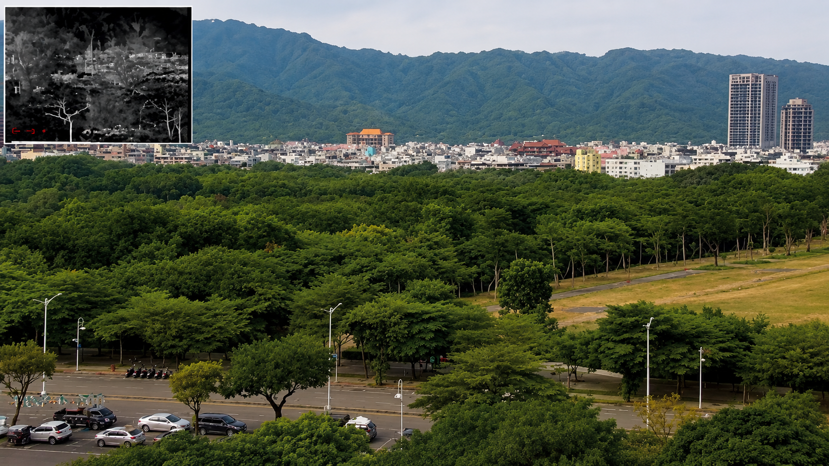
Picture-in-picture (PiP) mode brings that same two-stage architecture into the user interface. The operator can view both the wide-field thermal imaging channel and the narrow-field visible-light channel simultaneously within a single window, switching the primary view with a single click.
The interface reflects the underlying system architecture rather than simply presenting two video streams.
What must be considered during system design. Cueing accuracy is determined not by the software, but by the platform mechanics and system alignment:
- the angular accuracy of the pan-tilt platform encoders;
- the alignment of the platform to true north;
- the accuracy of the digital magnetic compass, as well as the effects of magnetic declination and local magnetic deviation caused by nearby metal structures;
- the accuracy of the support structure’s geodetic survey.
A one-degree compass error introduces the same pointing error as a one-degree radar error.
Stage 3. Track Management
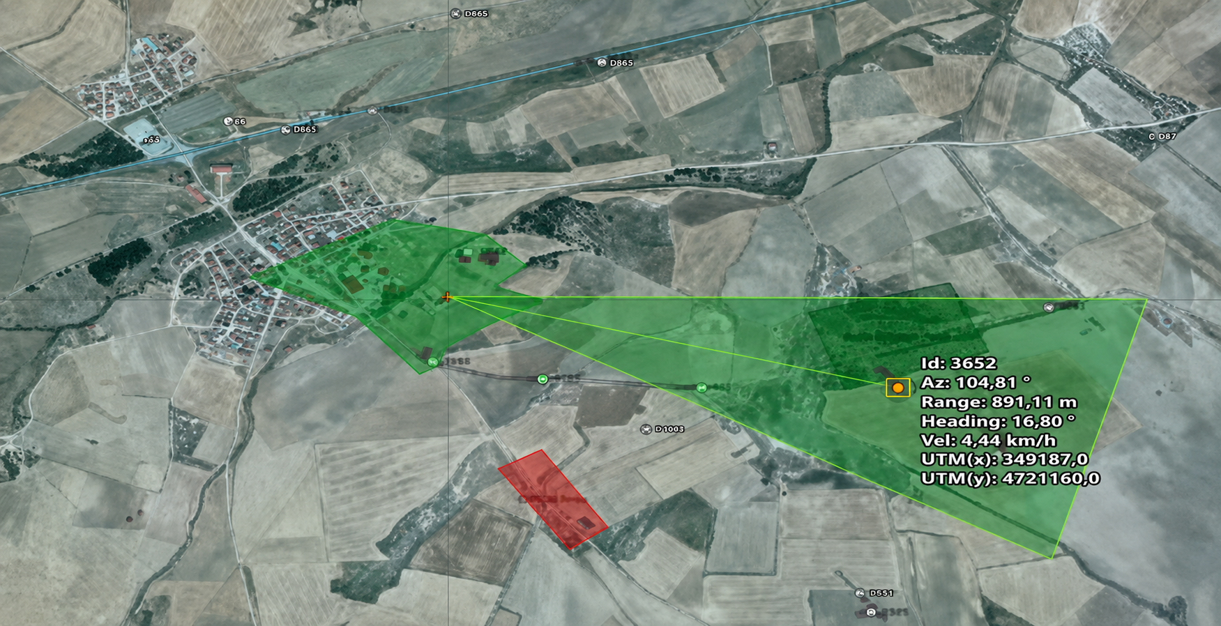
The illustration shows the information contained in a track: the target ID, range, heading, speed, and coordinates in the UTM coordinate system.
Це важлива деталь для інтеграції. Радар працює у власній полярній системі відносно свого положення. Камера — у системі поворот-нахил відносно своєї опори. Карта — у прямокутних координатах UTM. Кожен перехід між цими системами потребує точно відомого положення та курсу відповідного пристрою. Помилка у вивірці однієї опори проявиться як систематичне зміщення всіх цілей, яке в експлуатації діагностується важко.
Віртуальні заборонені зони, задані на карті, працюють у координатах місцевості й від наведення камери не залежать. Це коректне рішення.
Stage 4. Identification and Classification
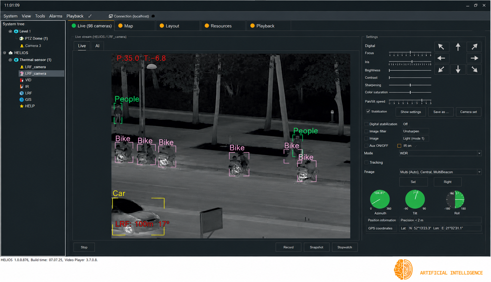
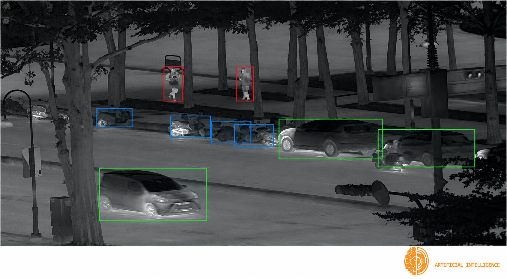
Confirmed capability
HELIOS C2 performs neural network–based object detection and identification with autonomous false-positive rejection. The system provides 12 predefined object classes covering aerial, ground, and maritime targets. Operators can configure which classes generate alarms and which are automatically ignored.
Engineering interpretation
There is no single, universal classification accuracy figure—and that is a property of the problem itself. Performance depends on the sensor and optics, target range, viewing angle, target-to-background contrast, time of day, and atmospheric conditions.
The same principle applies to the number of analytics streams that can run simultaneously on the GPU. Capacity depends on image resolution, frame rate, and the set of enabled object classes. As a result, these figures can only be established for a specific system configuration during the design and validation phases. Only then do they have practical engineering value.
How to interpret demonstration materials
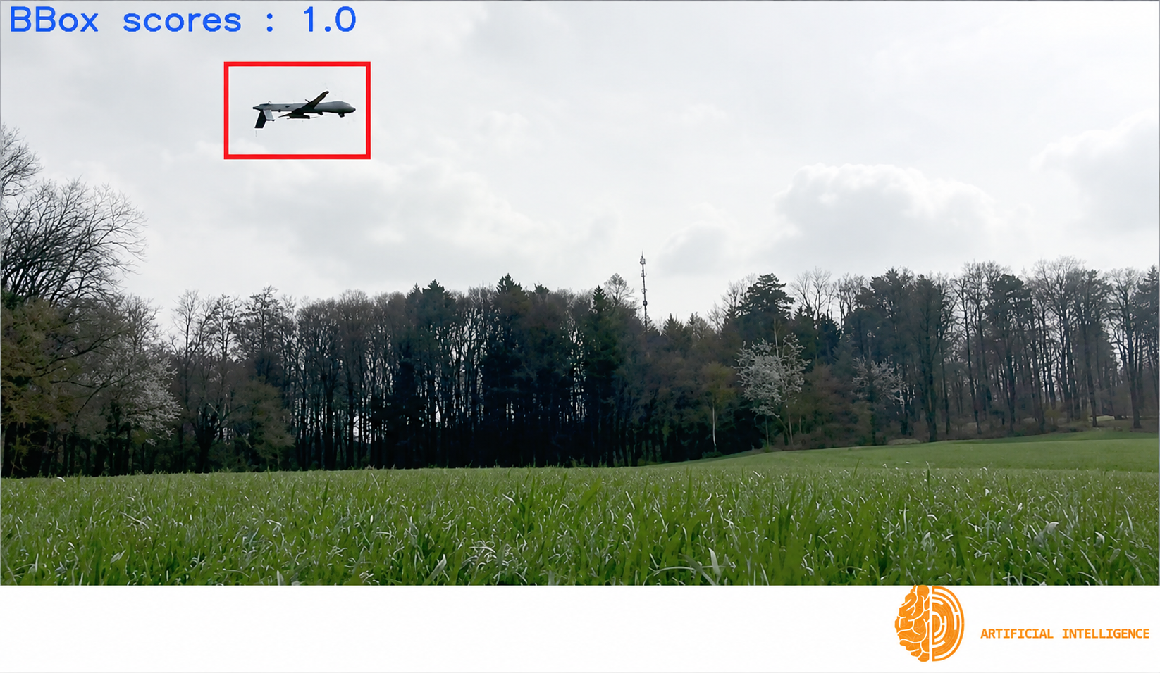
Labels such as Bbox scores: 1.0 or summary indicators like 100% classified in presentation screenshots illustrate the user interface—they do not represent the system’s classification accuracy. The former shows the detector’s confidence for a single detection in a specific frame, while the latter is simply an example of how the reporting dashboard is populated.
This is standard practice across the industry. Such values are intended to demonstrate the interface and workflow, not to quantify product performance.
The upper limit of what is achievable is set by physics—and it can be calculated in advance. As the analysis in Part 1 showed, if a target occupies fewer than eight pixels, no algorithm can reliably distinguish a person from an animal because the required information simply is not present in the image.
Below that threshold, performance must be established through field validation. This should be treated as a dedicated project phase, with the test ranges and environmental conditions defined in advance.
Stage 5. Geolocation
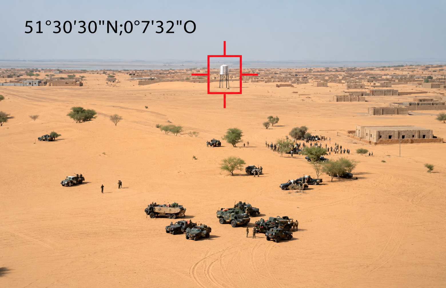
Confirmed capability
When used together with a digital compass and a laser rangefinder, HELIOS C2 calculates the geographic coordinates of a distant target. The manufacturer explicitly notes that without a laser rangefinder, and relying on the digital compass alone, the calculated coordinates are approximate.
Why this matters
Determining a target’s position requires both direction and range. A laser rangefinder provides the range through direct measurement. Without it, the system must assume that the target lies on the ground surface defined by a known terrain elevation model. The error introduced by that assumption increases with both distance and terrain variability.
What limits accuracy when a laser rangefinder is available
A laser rangefinder in this class typically provides range measurements with an error on the order of a few meters, largely independent of distance. Azimuth error behaves very differently: an error of one degree corresponds to 87 meters at a distance of 5 km.
As a result, geolocation accuracy is determined not by the rangefinder, but by the quality of the platform’s angular alignment. That, in turn, directly affects whether the resulting coordinates are accurate enough to be shared with adjacent services and response teams.
Stage 6. Image Management
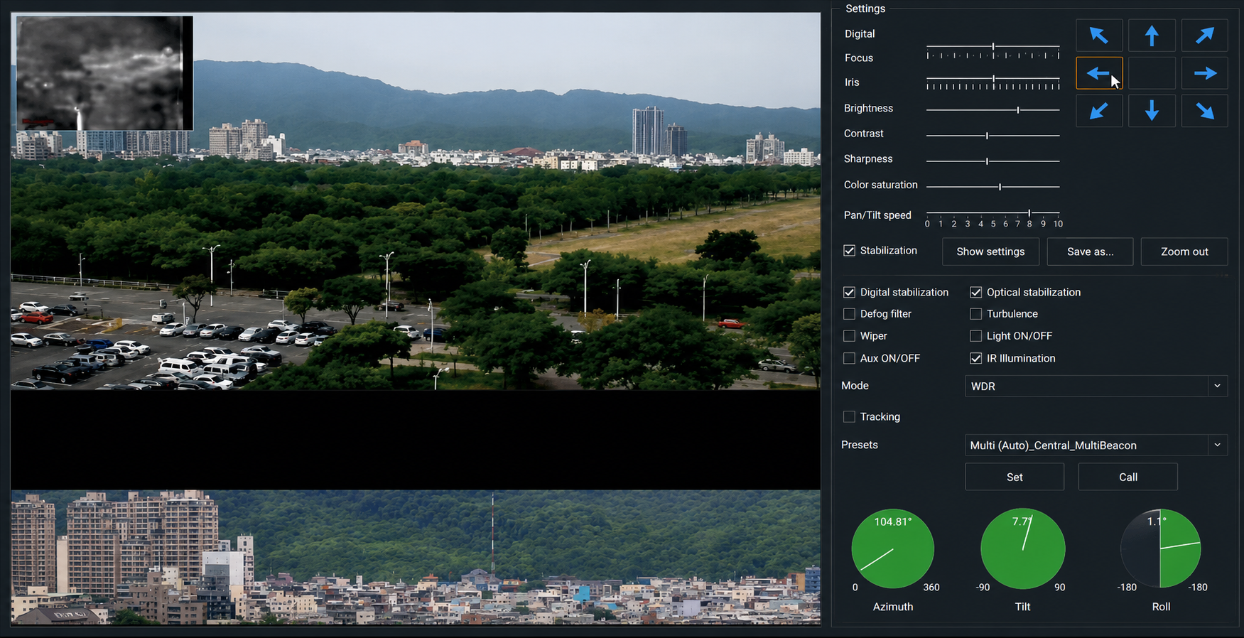
The control panel includes two features that directly address the physics of long-range observation: haze reduction and atmospheric turbulence compensation. The presence of a dedicated turbulence compensation tool indicates that atmospheric turbulence is treated as a normal operating condition at long ranges, rather than an exceptional one.
The same panel provides access to range measurement, target coordinates, azimuth, pan, and tilt indicators, optical and digital image stabilization, and preset positions. The status bar also displays client-side CPU, system memory, and GPU memory utilization.
This last detail deserves separate attention. An application that exposes GPU memory utilization to the operator makes it possible to identify performance degradation before it develops into a system failure. In a system where analytics are processed locally on the GPU, this provides a practical built-in measurement tool during testing.
Part 3. What HELIOS C2 Actually Is
HELIOS C2 is a perimeter security software platform that integrates video, thermal imaging, radar, and other sensors to detect intrusions. It is not a video management system, but a dedicated command-and-control layer that manages sensors, tracks, and target engagement.
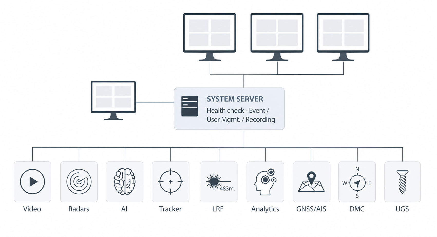
The system server is responsible for system health monitoring, event management, user management, and recording. It integrates nine categories of data sources:
- video;
- radar;
- the AI module;
- the tracking engine;
- the laser rangefinder;
- analytics modules;
- GNSS and the Automatic Identification System (AIS);
- the digital compass;
- underground sensors.
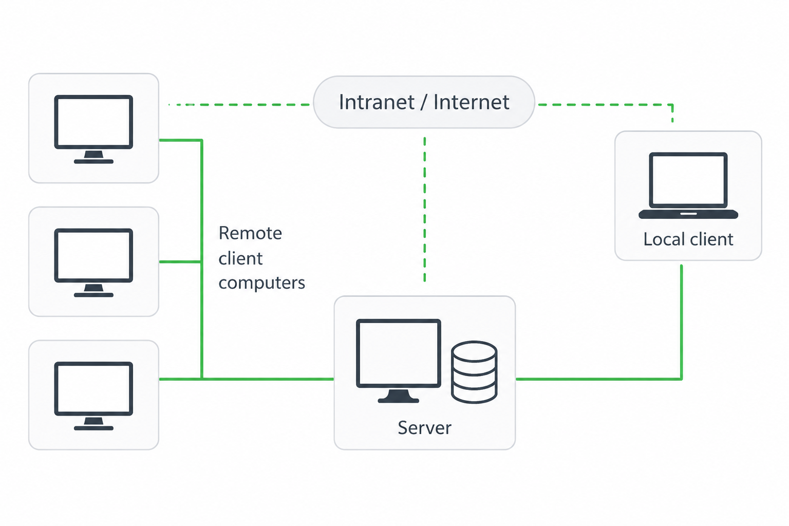
Deployment model. HELIOS C2 can be deployed either as a standalone installation or as a client-server system with remote operator workstations connected over a local network or the Internet.
Integration model. Device integration is provided through hardware-specific integration drivers.
Minimum system requirements:
- a 13th-generation Intel Core i9 processor or newer;
- Windows 10 or 11;
- 32 GB of RAM;
- an NVIDIA GPU with 12 GB GDDR6X memory for analytics functions;
- 1 TB of system storage plus a dedicated high-speed data storage volume.
Requirements for automatic target tracking and compatibility with hardware-specific integration packages are specified separately.
NATO Codification System registration. The company holds NCAGE code SHCT4, indicating that it is registered in the NATO Codification System as a supplier. This is a relevant qualification for defence procurement processes. It does not, however, indicate the technical maturity or operational performance of a specific product. Those must be assessed separately through testing and operational experience.
Response: Relay Control
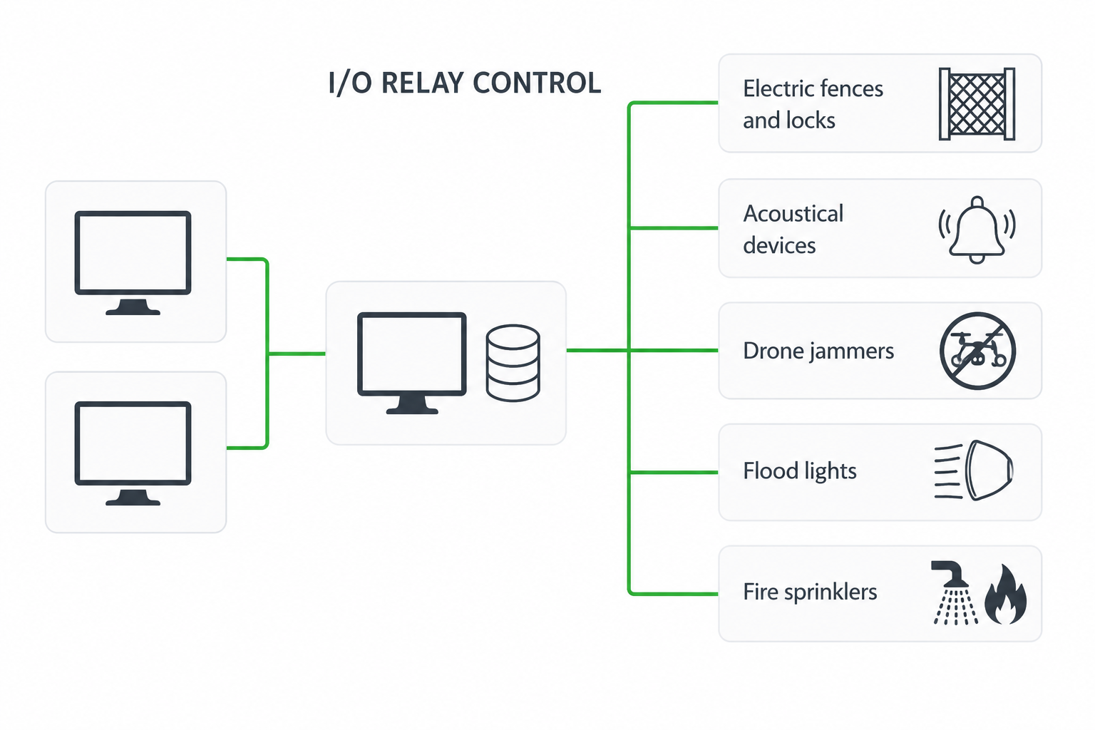
In response to a system alarm, the platform can switch external electrical circuits through its relay outputs. This turns detection into an automated response without relying on a separate automation system. At the same time, it makes relay configuration part of the operational response logic—something that must be engineered, validated, and tested alongside the rest of the system.
Database and Reporting
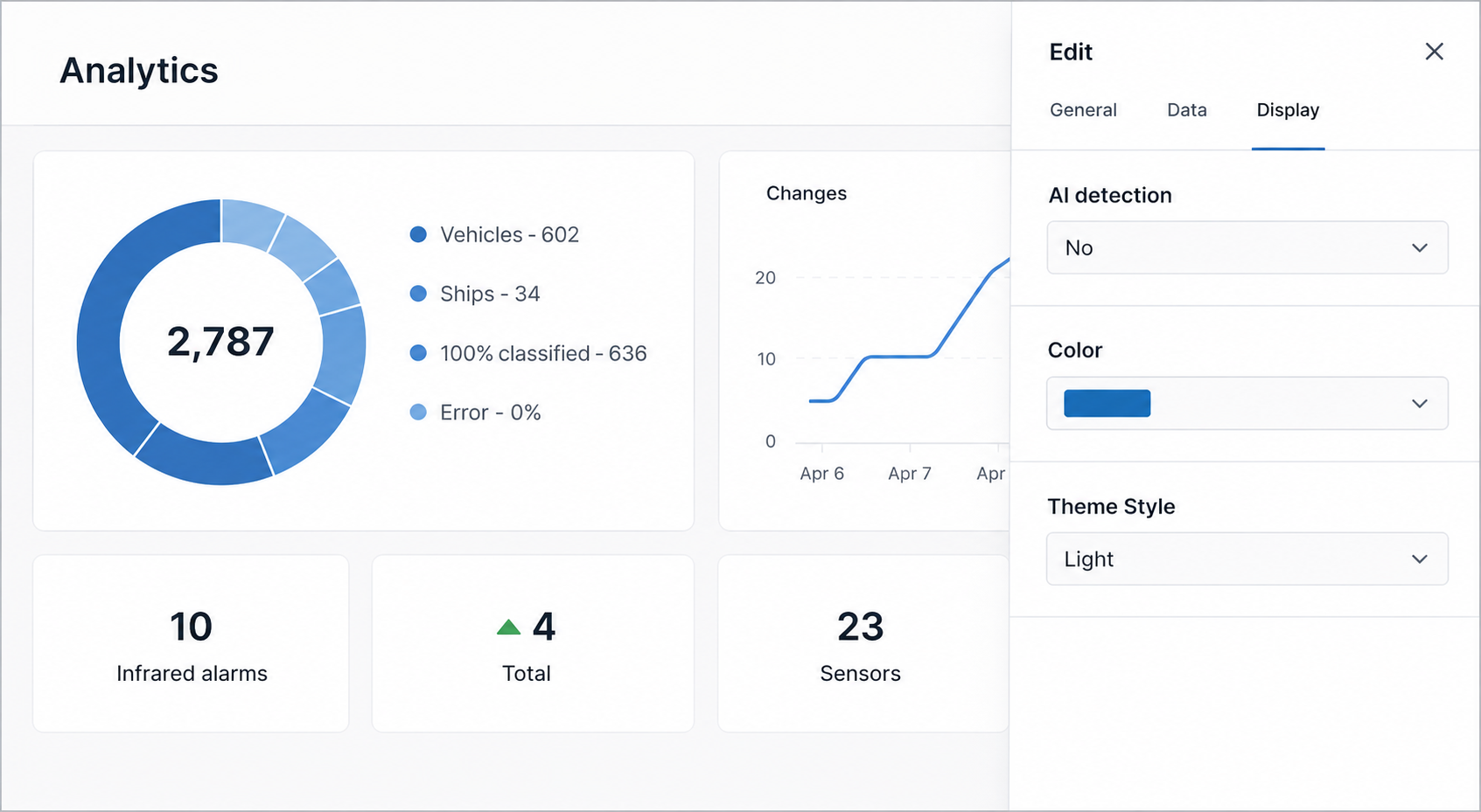
The reporting module supports filtering by alarms, classified objects, time, and location. Visually, the reporting interface is implemented as a dedicated web application separate from the main operator client.
The choice of database management system, storage architecture, and data retention policy depends on the requirements of the specific deployment.
Deployment Models
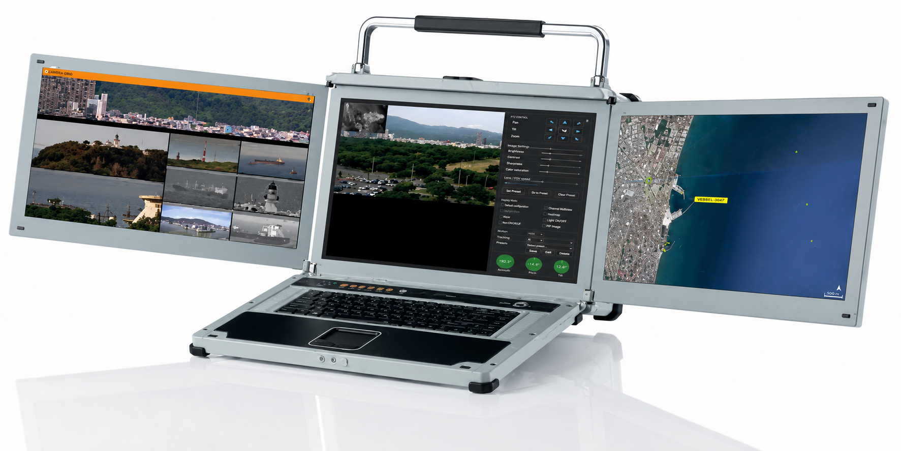
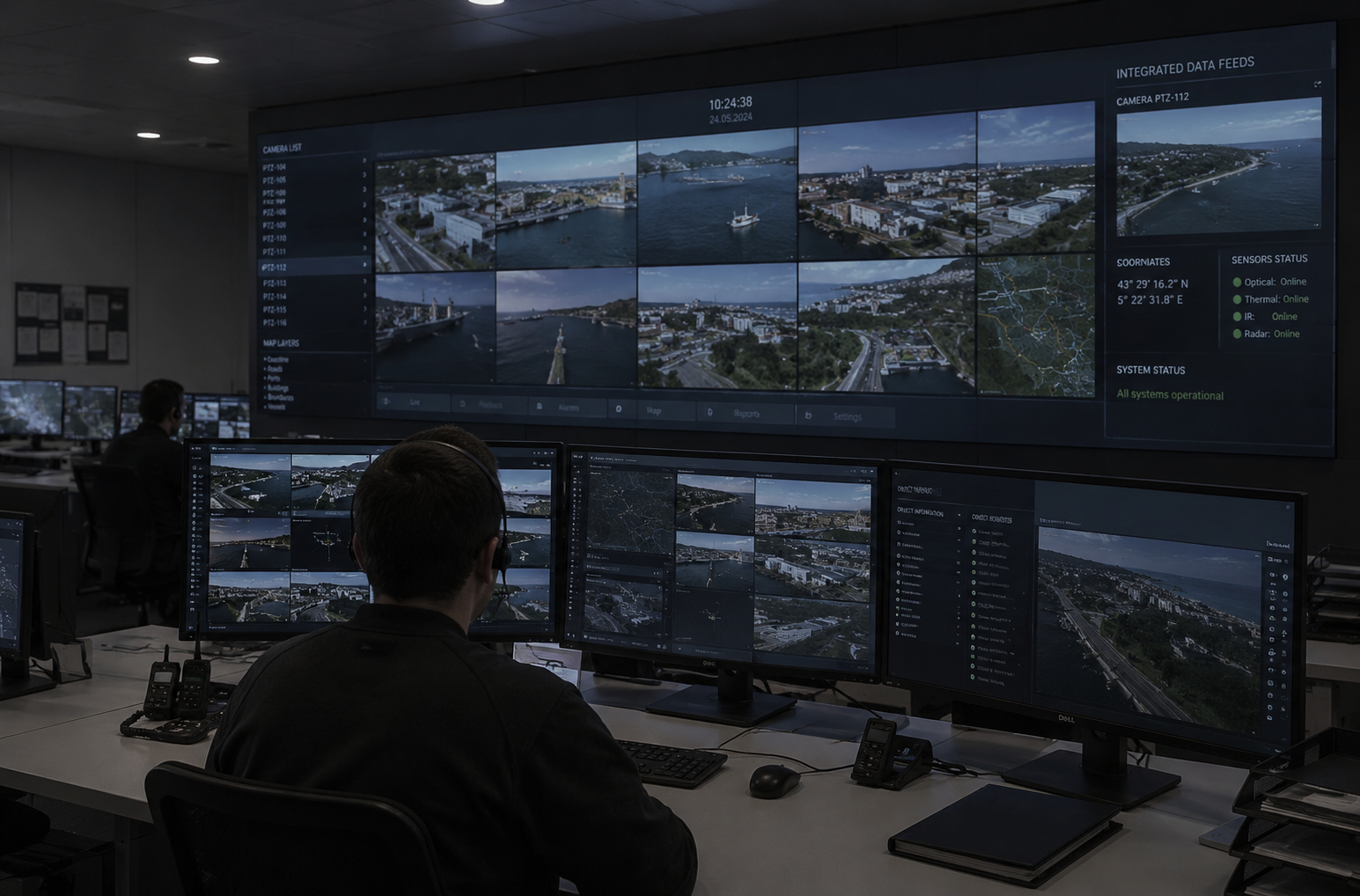
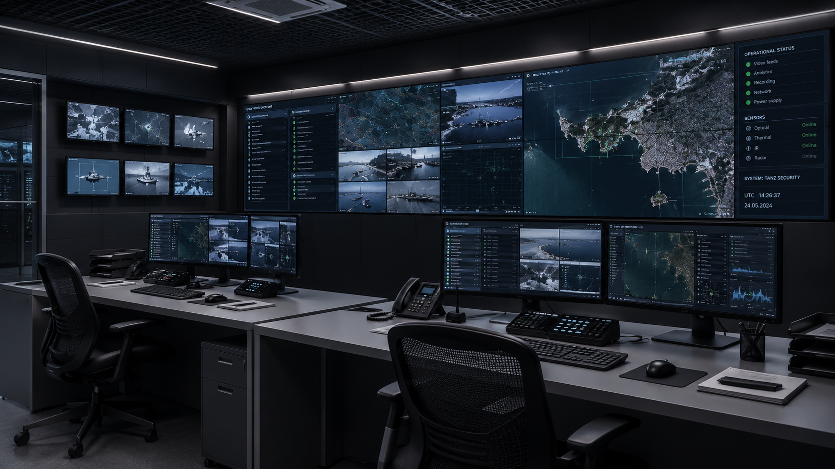
The platform is available either as a software package for installation on customer-supplied hardware or as part of a rugged multi-display laptop solution. Deployment scales from a single tactical workstation to a full control room with a video wall.
ANVR Component
The platform documentation identifies ANVR as a dedicated component responsible for neural-network object detection and relay output control. According to the documentation, it provides AI-based detection across twelve predefined object classes and supports event-driven control of external devices through relay outputs.
The scope and boundaries of the ANVR component should be clarified during specification development. If the analytics layer and relay output control are supplied as a separate product or licensed component, they may have their own licensing model, hardware requirements, and lifecycle. This affects both the system bill of materials and the project budget. Clarifying these points during the preparation of the commercial proposal helps avoid integration and procurement issues later in the project.
Part 4. What Belongs Outside HELIOS C2
The command-and-control platform is responsible for sensor integration and target management. Alongside it, the system architecture includes an adjacent system layer responsible for:
- scalability and licensing model;
- storage sizing, archive retention, codecs, and recording redundancy;
- fault tolerance, clustering, and system behavior in the event of a server failure;
- database management system;
- role-based access control and operator activity logging;
- platform security, including operating system hardening, stream and database encryption, and network authentication.
These functions typically belong to an enterprise-class video management system rather than the command-and-control layer. The separation of responsibilities is intentional: each layer addresses the problems it is designed to solve, and large-scale deployments generally require both.
Problems arise when the project documentation does not explicitly assign responsibility for each of these functions to a specific subsystem. In that situation, a default assumption often takes hold: everyone expects the VMS to provide the archive, operator accounts, and security controls.
But if the solution includes only the command-and-control platform and no VMS, those functions may end up with no clear owner at all. This is often discovered only during deployment, when changing the architecture is already both costly and disruptive.
The practical rule is straightforward: the allocation of responsibilities between architectural layers should be documented before implementation begins. The project documentation should explicitly identify which layer is responsible for archive management, operator accounts, cybersecurity, and the other supporting functions.
A single page defining these responsibilities is often enough to eliminate many of the integration issues that would otherwise surface during commissioning.
Part 5. Defining the Boundary: Three Architectural Options
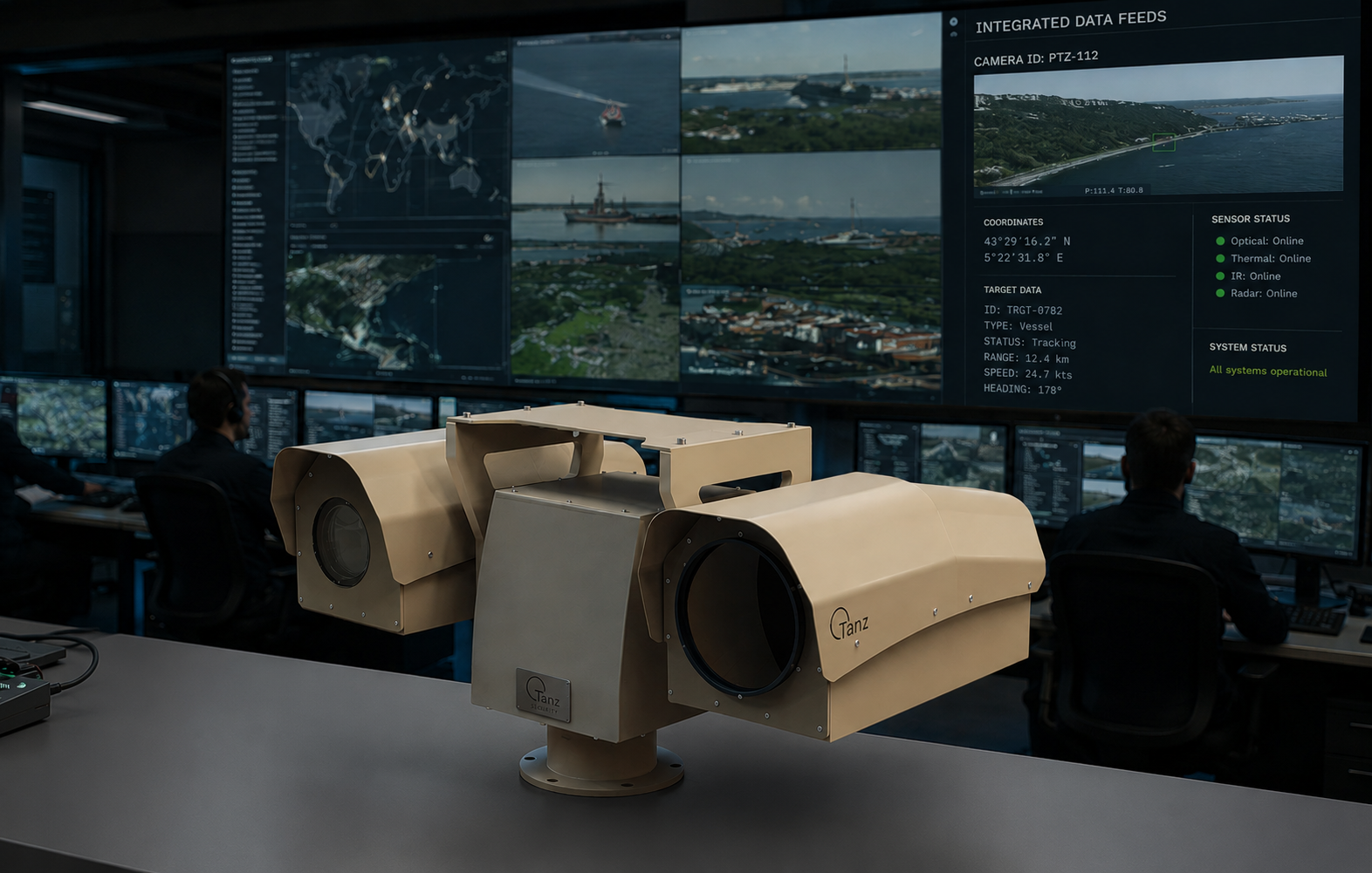
Option A. Command-and-Control Platform Only
The platform is deployed as a standalone system without an external video management system (VMS).
When it makes sense. This architecture is well suited to deployments with a small number of multisensor systems, tactical or mobile applications, and standalone sites with a local operator. It is also appropriate where archive retention requirements are minimal or nonexistent and where integration with an enterprise directory service is not required.
What comes with this choice. Responsibility for archive management, user accounts, and cybersecurity remains within the platform, and their implementation should be agreed with the vendor for the specific deployment. Scalability beyond a small number of multisensor systems should be verified as part of the system design.
Option B. Video Management System Only, with Cameras Connected Directly
Tanz multisensor systems are integrated into an existing enterprise video management system (VMS) as network cameras.
When it makes sense. This architecture is well suited to environments where long-range multisensor systems represent only a small part of a much larger video surveillance deployment. The primary requirements are centralized archive management, incident investigation, and a unified user management system.
What comes with this choice. This architecture does not typically provide the capabilities that justify a dedicated command-and-control layer: cueing from external sensors, radar track integration, target geolocation, and the two-stage acquisition workflow. In this configuration, the multisensor system effectively operates as a long-range network camera, which is sufficient for many surveillance applications.
One aspect should be verified separately: the quality of pan-tilt-zoom (PTZ) control provided by the VMS. At focal lengths of several hundred millimetres, the positioning resolution that is acceptable for a conventional PTZ camera may prove insufficient for accurate long-range target acquisition.
Option C. Command-and-Control Platform with an Enterprise VMS
The command-and-control platform is responsible for sensor integration and target management, while the video management system (VMS) provides archive management, user management, and cybersecurity. The boundary between the two is explicitly defined as part of the system architecture.
When it makes sense. This architecture is appropriate for sites that combine long-range perimeter surveillance with a mature video management system. It is particularly relevant where evidentiary video retention and centralized authentication are required.
What comes with this choice. This architecture introduces an integration boundary, and that boundary should be documented explicitly. The mechanism for exchanging events between the command-and-control platform and the VMS must be agreed for the specific integration and implemented by the vendor. As a result, updates to either system should be treated as controlled changes requiring compatibility verification before deployment.
Responsibility Matrix
Function
Option A
Option B
Option C
Cueing from external sensors
Option AC2
Option Bnot available
Option CC2
Radar track integration and target geolocation
Option AC2
Option Bnot available
Option CC2
Object classification
Option AC2
Option BVMS or camera
Option Cto be agreed; potential functional overlap
Video archive and retention
Option AC2; deployment-specific
Option BVMS
Option CVMS
User management
Option AC2
Option BVMS
Option CVMS
Cybersecurity and network authentication
Option Ato be agreed
Option BVMS
Option CVMS
Scalability to hundreds of channels
Option Ato be verified
Option BVMS
Option CVMS
Integration boundary between layers
Option Anone
Option Bnone
Option Crequires an integration specification
What the matrix shows
Option C provides the broadest functional coverage while introducing an integration boundary that must be defined and documented. Whether this additional complexity is justified depends on the importance of long-term video retention, centralized authentication, and the other enterprise capabilities provided by the VMS.
Part 6. Operational Considerations
The following sections highlight the parameters that have the greatest impact on operational performance and should be considered during the system design phase.
Integration through proprietary drivers
A dedicated driver for each supported device enables a deeper level of integration than generic industry-standard protocols. Standard interfaces typically cannot carry data such as laser rangefinder measurements, digital compass heading, or radar tracks. The trade-off is tighter vendor dependency: support for new sensor types and additional devices is implemented by the vendor, and firmware updates for any device in the integration chain should be treated as controlled changes requiring compatibility verification. The list of devices with existing driver support, together with the process for adding new devices, should be confirmed with the supplier during specification development.
A single GPU
The published minimum system requirements describe a configuration with a single graphics processor. The number of concurrent AI inference streams depends on image resolution, frame rate, and the selected object classes, and therefore must be determined by performance testing for the target configuration rather than by specification alone. The GPU memory utilization indicator in the client application provides the standard operational metric for this validation.
Operating system lifecycle
The platform is supported on Windows 10 and Windows 11. Mainstream support for Windows 10 ended on 14 October 2025; after that date, security updates are available only through the time-limited Extended Security Updates (ESU) program.
For critical infrastructure deployments, this becomes a lifecycle management issue rather than simply an operating system choice. The target operating system, the migration strategy, and the process for maintaining vendor support throughout the system lifecycle should all be defined during the system design phase.
Virtual Tripwires on a PTZ Camera
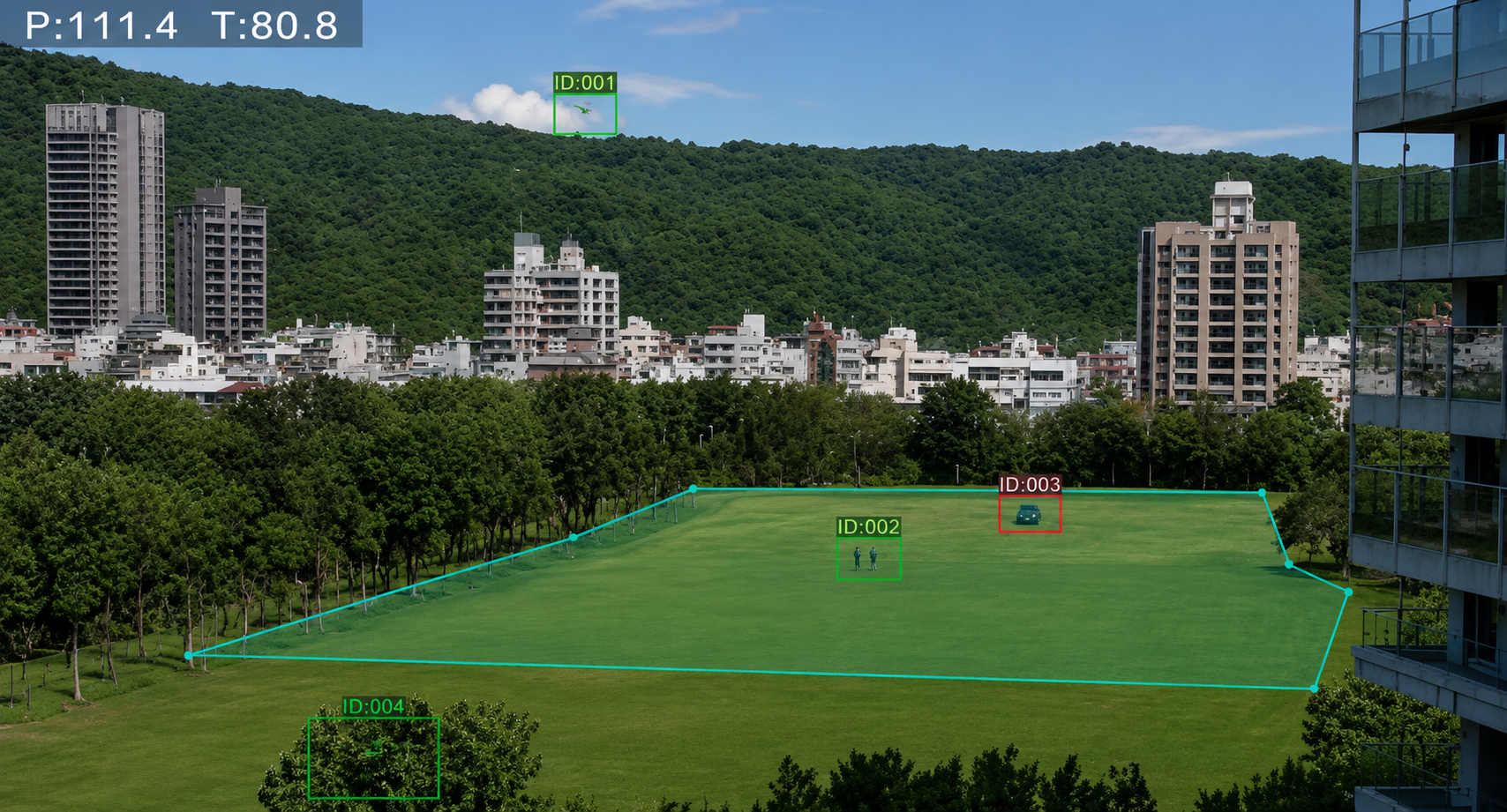
A virtual tripwire defined within the camera image is tied to a specific pan-tilt-zoom (PTZ) position. After the camera is slewed to another target, the tripwire becomes active again only when the platform returns to the same position. Whether tripwires are associated with PTZ presets or with real-world coordinates should be confirmed for the intended deployment scenario. This is a practical design consideration: if the same multisensor system is expected to guard a virtual perimeter while also responding to external target cues, the two functions compete for the same mechanical platform.
Panoramic Image as a Reference View
As discussed in Part 1, the panoramic image serves as a navigation aid rather than a live video source. The current operational picture is provided by the sensors in real time.
The Role of the Laser Rangefinder in Geolocation
The manufacturer explicitly states that, without a laser rangefinder, target geolocation is only approximate. This requirement should be carried through into the technical specification rather than left as an implementation detail.
Part 7. What to Verify Before System Design
The following checklist is not specific to HELIOS C2. It is equally applicable to any command-and-control platform in this class. The questions are grouped according to their purpose: the first define the system specification, the next address the system architecture, and the final group should be verified during deployment and acceptance testing.
Questions Affecting the System Specification
- Is the ANVR component supplied as part of HELIOS C2 or as a separate product? How is it licensed, and what are its hardware requirements?
- How are events and alarms exported to external systems?
- What is the licensing model: by the number of sensors, operator workstations, servers, or AI inference streams?
- How many concurrent AI inference streams does the minimum recommended hardware configuration support? For which object classes, at what image resolution, and at what frame rate?
Questions Affecting the System Architecture
- Which database management system is used? What video storage model and retention policy are supported?
- Is server redundancy supported, and how does the system behave in the event of a server failure?
- What role-based access model is implemented, and are operator actions logged?
- Which security mechanisms are provided, including stream and database encryption, operating system hardening, and network authentication?
- What is required to migrate an operational system to a newer version of the operating system: reinstallation, relicensing, or reconfiguration of integrations?
Questions to Be Verified During Deployment and Acceptance Testing
Some parameters cannot be established from documentation alone and must be measured on the target site. These include the maximum range for reliable object classification under site-specific conditions, the actual success rate of target cueing from the installed radar, geolocation accuracy measured against surveyed reference points, and the utilization of the computing module under the expected analytical workload.
The test programme should be tailored to the specific site and should satisfy two essential requirements; otherwise, it becomes little more than a demonstration. First, each measurement should have an acceptance criterion agreed in advance. Second, testing should be performed under the worst expected operating conditions rather than under the most favourable ones. For long-range optical systems, the most demanding conditions are typically encountered around midday over sun-heated surfaces.
For a mobile system, the test programme is fundamentally different. A fixed installation is surveyed once, after which testing focuses on the accuracy of the system itself. In a mobile deployment, the angular reference must be re-established every time the system is deployed. The key performance measures therefore become the repeatability of the alignment procedure and the time required for a standard operating crew to bring the system to operational readiness.
The Role of the Engineering Partner
Most of the questions in this checklist cannot be answered from publicly available information, and that is entirely normal for systems of this class. Detailed technical documentation is typically provided under a non-disclosure agreement (NDA), while some characteristics depend on the specific system configuration and therefore do not exist as universal specification values.
Problems arise when these questions are not asked at all. In that case, the system architecture is built on assumptions that often have to be revisited during commissioning, when changes are significantly more disruptive and costly.
FortiSec specializes in this stage of the project. Its portfolio includes both command-and-control platforms for long-range multisensor systems and enterprise-class video management systems, allowing the architectural boundary between the two layers to be defined without bias toward a particular product. In practice, this means verifying the site geometry and calculating detection ranges for the selected sensors, coordinating the specification questions listed above with the manufacturer, preparing the acceptance test programme, and documenting the allocation of responsibilities between the command-and-control platform and the VMS before implementation begins.
This work does not result in a specification alone. Its outcome is a clear system architecture with explicitly defined conditions of use, responsibilities, and operational boundaries.