Engineering Case Study
Enhancing Operational Safety and Process Visibility in High-Temperature Metallurgical Production
- FacilityMetallurgical plant, Ukraine
- ScopeMore than 30 heat-resistant camera modules
- Equipment supplierGlobal Proof (Italy)
- Engineering adaptation and implementationUkrbudproekt Plus LLC
- Base solutionGlobal Proof CRL Series protective housings
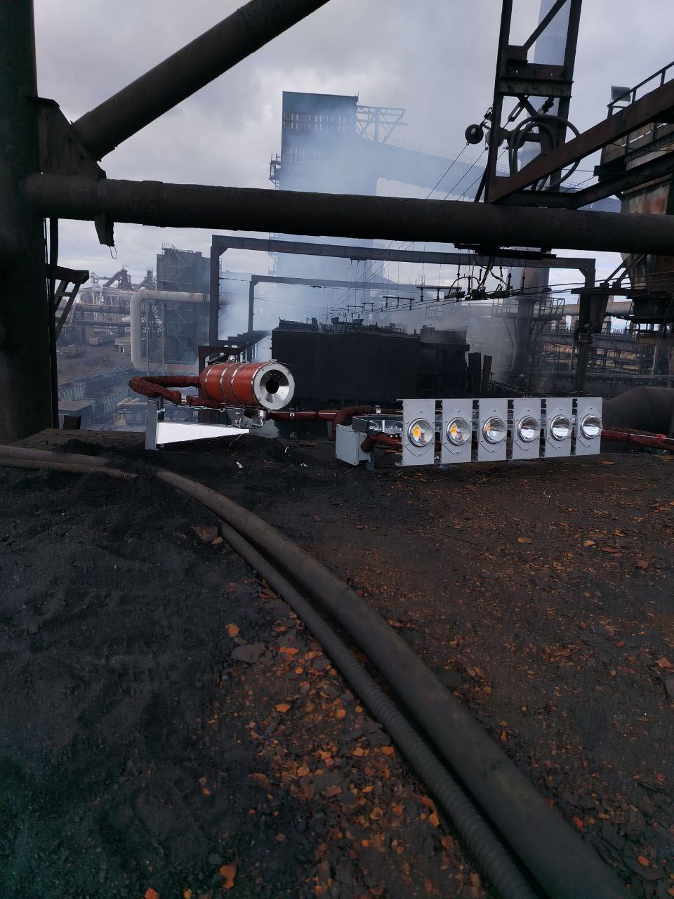
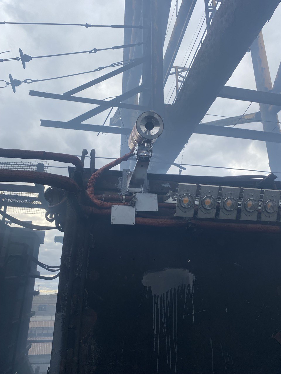
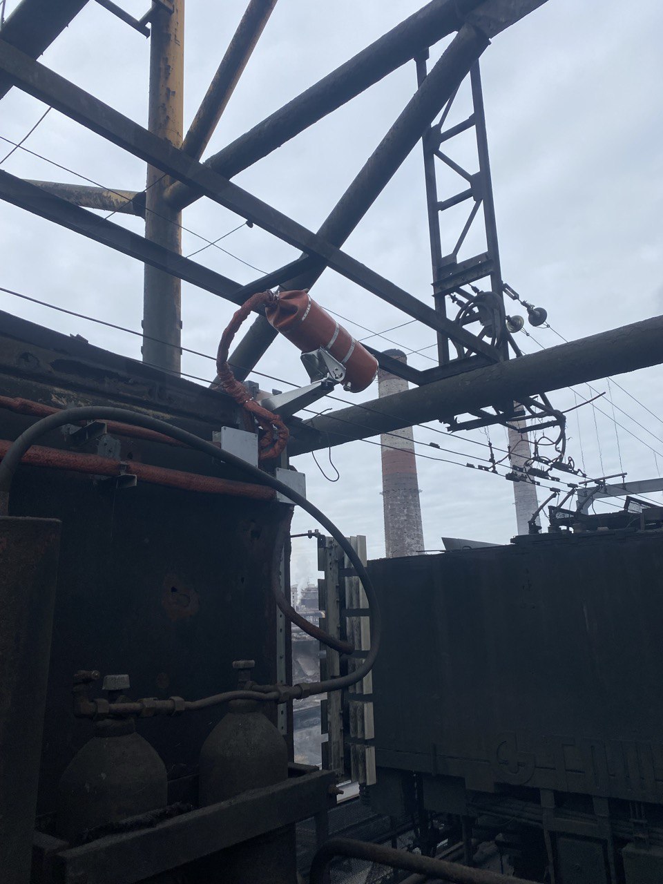
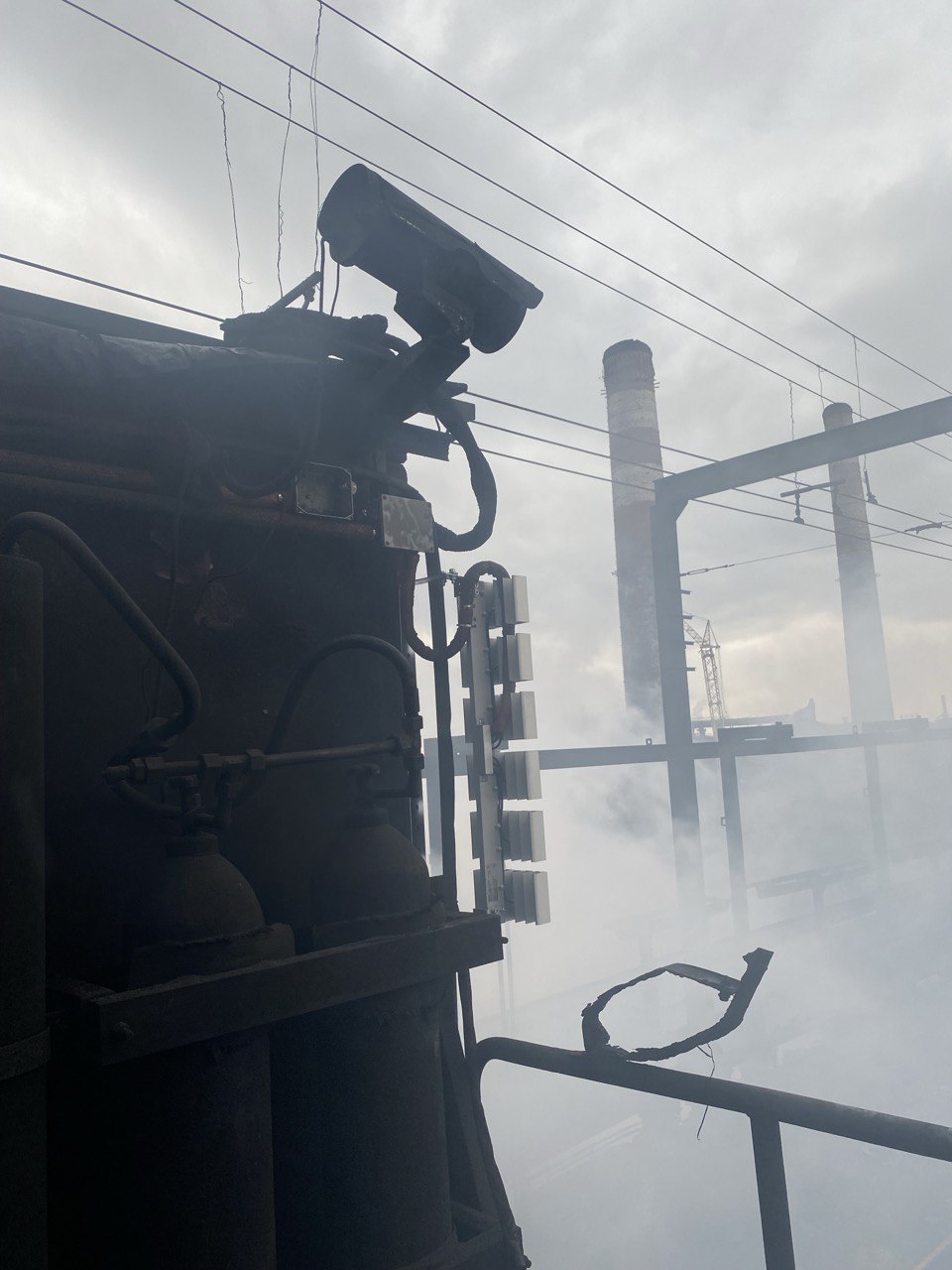
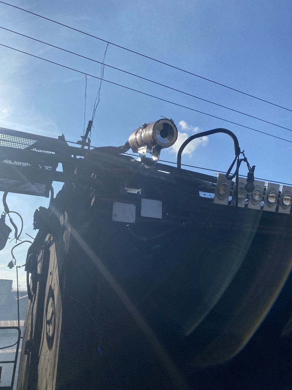
One of Ukraine’s largest deployments of high-temperature industrial video monitoring systems has been successfully implemented at a major metallurgical plant. More than 30 heat-resistant camera modules were installed across critical process areas operating under extreme thermal conditions, providing continuous visual monitoring where conventional imaging equipment cannot function reliably.
The solution combined proven international technology with local engineering expertise. Heat-resistant camera housings supplied by Italian manufacturer Global Proof were integrated into the production environment through the engineering and system adaptation performed by Ukrbudproekt Plus LLC. This collaboration ensured reliable operation under the plant’s demanding thermal and environmental conditions.
This case study explains the engineering approach behind the project—from the challenges of continuous video monitoring in extreme-temperature environments to the design choices that enabled reliable operation. It also examines the performance boundaries of the solution and the operating conditions for which it was specifically engineered.
The Challenge
The most critical areas of a metallurgical plant—including casting lines, furnace zones, and molten metal transfer routes—are also the most challenging environments for video monitoring. Extreme temperatures, airborne dust, and radiant heat rapidly degrade conventional camera systems, resulting in blind spots not because cameras are absent, but because they can no longer deliver reliable visual information after only a few months of operation.
The project’s objective was not simply to deploy 30 camera units, but to provide continuous, reliable video monitoring in process areas where conventional imaging systems cannot operate effectively over the long term.
Why Standard Outdoor Protection Is Not Enough
The failure of conventional camera systems in high-temperature environments is driven by three distinct mechanisms, each requiring a different engineering approach.
The first challenge is radiant heat
Ambient air temperature alone is a poor indicator of the thermal load acting on a camera housing. In the vicinity of molten metal, thermal radiation becomes the dominant mode of heat transfer, with heat exposure determined primarily by the camera’s distance from and orientation to the heat source. As a result, two cameras installed in the same production area may experience dramatically different thermal loads despite identical ambient conditions. For this reason, camera placement is an engineering design decision rather than a routine installation task.
The second challenge is optical degradation, which typically occurs long before electronic failure
Scale, dust, and other process by-products gradually accumulate on the housing’s viewing window. Although the camera itself remains fully operational, image quality deteriorates to the point where it no longer provides reliable information for process monitoring. From an operational perspective, this represents a system failure, even though the electronics continue to function as designed.
The third challenge is corrosion
Exposure to industrial chemicals, condensate, and chloride-containing contaminants can significantly reduce the service life of conventional aluminum and polymer camera housings. Over time, corrosion compromises structural integrity, sealing performance, and long-term reliability, increasing maintenance requirements and the risk of premature equipment replacement.
Engineering the Right Protection Platform
Based on these operating requirements, the CRL150 protection platform was selected. Its design combines a hermetically sealed cylindrical enclosure, a double-chamber liquid-cooling system, and an integrated air barrier to address the three primary failure mechanisms encountered in high-temperature process areas. Rather than relying on a single protective measure, the platform applies complementary design features to maintain reliable operation under extreme industrial conditions.
AISI 316L stainless steel. A low-carbon austenitic chromium-nickel-molybdenum stainless steel selected for its corrosion resistance and weldability in demanding industrial environments. The addition of molybdenum improves resistance to pitting and crevice corrosion, particularly in chloride-containing atmospheres, while the reduced carbon content minimizes the risk of carbide precipitation in welded joints. Rather than representing a universally superior material, AISI 316L was selected because its properties align with the mechanical, thermal, and corrosion requirements of a welded enclosure operating in harsh metallurgical conditions.
Cylindrical geometry. The cylindrical enclosure enables a continuous annular cooling circuit, reducing temperature gradients across the housing and minimizing localized thermal stresses that typically develop in rectangular enclosures.
Double-chamber construction. The cooling medium circulates through a dedicated outer chamber, while the camera and electronics remain enclosed within a separate sealed compartment. This configuration provides effective heat dissipation without exposing critical components to the cooling circuit.
Front air barrier. The integrated air barrier protects the viewing window—the component most vulnerable to contamination and thermal loading. A controlled airflow cools the front section of the housing while reducing the accumulation of dust and process by-products on the optical surface, helping maintain image quality during continuous operation.
“Compressed air is directed through the front air barrier to protect the viewing window. The resulting airflow limits the accumulation of dust and process by-products while providing localized cooling of the front assembly,” explains the project engineer.
In this design, the sunshield serves a fundamentally different purpose than on conventional CCTV cameras. Rather than acting as a simple weather visor, it functions as an integral part of the thermal management system, providing both optical protection and localized cooling of the viewing window.
The key design principle is that thermal protection is achieved through active heat removal rather than passive insulation. As a result, the housing cannot operate as a standalone device—it must be connected to plant utilities, using either a cooling-water supply or compressed air, depending on the configuration.
From an engineering perspective, this fundamentally changes the scope of the project. The primary challenge is not installing the cameras themselves, but designing and routing the cooling infrastructure to every installation point. In large-scale deployments, the cooling network becomes a critical part of the overall system architecture.
Engineering Implications of Active Cooling
The manufacturer provides indicative operating points for the cooling system: at an ambient temperature of 200°C, the required coolant flow rate is approximately 2 L/min; at 300°C, 2.4 L/min; and at 400°C, it increases to 6.8 L/min. The relationship is clearly non-linear—between 300°C and 400°C, the required flow rate nearly triples.
For the system designer, these figures are more than reference values. They demonstrate that cooling demand cannot be estimated by linear extrapolation from a single operating point. Instead, each installation location must be evaluated individually based on its specific thermal load, with the cooling infrastructure sized accordingly.
The manufacturer specifies compressed air as an alternative cooling medium only for ambient temperatures up to 80°C. Beyond this threshold, air cooling cannot replace the water-cooled configuration.
As a result, the choice of cooling method is not driven by installation convenience but by the actual thermal conditions at each installation point. The site’s thermal profile ultimately determines where compressed-air cooling is sufficient and where water cooling is required.
This introduces an architectural implication that should be considered from the earliest stages of system design. The availability of video monitoring in critical process areas no longer depends solely on the camera, network, and VMS—it also depends on the continuous availability of the supporting cooling infrastructure, whether a water supply or a compressed-air system.
This creates a critical infrastructure dependency.
The manufacturer’s public documentation does not describe built-in redundancy for the cooling infrastructure. Consequently, monitoring of cooling-system health—including pressure, flow, and fault conditions—as well as the need for redundant utility supplies, becomes a project-level architectural decision rather than a standard feature of the protective housing.
At the scale of 30 or more monitoring points, the cooling circuit should be treated as a dedicated plant utility rather than a feature of individual camera housings. Its distribution network, pumping or compressed-air equipment, and utility interfaces become integral elements of the overall system architecture, with direct implications for reliability, maintainability, and project execution.
Selecting the Right Viewing Window for the Application
The protective housing is available with several viewing-window options, each intended for a different operating scenario rather than representing a simple material variation.
- Standard glass supports visible-light cameras in environments up to 300°C, while the VHF150/B window extends the operating limit to 600°C for the hottest process areas.
- For thermal imaging applications, the housing is available with zinc selenide (ZnSe) windows, rated for ambient temperatures up to 200°C, or germanium windows, rated up to 80°C.
These lower temperature limits are determined by the physical properties of the infrared optical materials themselves rather than by the design of the protective housing.
The practical implication is that when thermal imaging is required—for example, to detect localized equipment overheating at an early stage—the maximum operating temperature may be determined by the viewing-window material rather than by the protective housing itself. In the hottest process areas, a thermal imaging configuration may therefore prove infeasible.
This compatibility should be verified during the requirements definition phase, before thermal imaging is incorporated into the system specification and project budget.
Engineering Planning Before Installation
Projects of this type cannot be scoped or budgeted by simply multiplying the cost of a protective housing by the number of cameras. Before the technical specification and project budget could be finalized, the engineering team first had to establish a set of project-specific parameters that are not provided in the manufacturer’s documentation:
- The thermal profile of every installation location, reflecting the actual heat load at each camera position rather than the average ambient temperature within the production area.
- The availability of plant utilities, specifically cooling-water or compressed-air infrastructure with sufficient capacity, or the additional work required to install these services.
- The requirement for thermal imaging at selected locations, which determines the choice of viewing-window material and, consequently, the configuration and cost of each camera assembly.
- The scope of supporting engineering works, including cooling-water pipework, compressed-air distribution, and other utility installations that extend well beyond the scope of a conventional CCTV deployment.
In practice, these engineering activities—not the selection of the protective housing itself—were the primary drivers of the project’s budget and delivery schedule. Unless they are identified and quantified during the planning phase, the true scope of utility infrastructure only becomes apparent during implementation, when changes are significantly more costly and disruptive.
Defining Engineering Responsibilities
The installation and long-term maintenance of the system extended well beyond the scope of a conventional CCTV deployment. In addition to electrical and network installation, the project required cooling-water pipework, compressed-air systems, and verification of coolant pressure and flow throughout the operating life of the installation.
These disciplines were incorporated into the project during the planning and resource estimation phase, with mechanical and piping expertise coordinated alongside the electrical and networking teams. Addressing these requirements before installation avoided costly changes to team composition and project execution after work had already begun.
At a deployment scale of more than 30 monitoring points, the project evolved into a proven reference implementation. It established a validated approach to cooling-circuit integration, pre-commissioning inspection procedures, and engineering practices that can be applied to future installations in high-temperature industrial environments.
As a result, similar systems can be deployed without repeating the entire engineering development process for each new site, provided that the associated mechanical, piping, and utility infrastructure is planned with the same level of engineering discipline.
Key Engineering Takeaways
The solution is most appropriate where the operating environment is characterized by sustained thermal loading, video monitoring performs a process-control function alongside its security role, and plant utilities make it practical to supply cooling water or clean compressed air to each installation point.
Cooling strategies were selected on a location-by-location basis. Where ambient temperatures remained below 80°C, the protective housing could operate using compressed-air cooling. In the hottest process areas, however, water cooling was required and, where necessary, the standard viewing window was replaced with the VHF150/B option to accommodate the higher thermal load.
These configurations were determined by the documented operating limits of each cooling and viewing-window option rather than by installation preference. Consequently, a deployment of more than 30 monitoring points could not be implemented using a single standard configuration; each installation location required an engineering solution matched to its specific operating conditions.
Conclusion
The project’s greatest engineering effort lay in the planning phase. Before installation could begin, the engineering team had to determine the thermal conditions at every camera location, design cooling circuits for the entire facility, and validate application-specific operating parameters with the manufacturer that were not covered by the published documentation.
Completing this work before construction began significantly reduced implementation risk and avoided costly engineering changes during installation.
FortiSec supports projects of this type as an engineering partner, assisting customers long before installation begins. This includes evaluating the thermal conditions at each installation location, validating application-specific operating parameters with the manufacturer where published documentation is insufficient, verifying camera compatibility with the protective housing in terms of dimensions and weight, and assessing cooling-water and compressed-air infrastructure requirements during the project planning phase.
If you are designing a video monitoring system for a high-temperature process area, provide the site conditions—including operating temperatures, distances from heat sources, and available cooling utilities—for an engineering assessment of the thermal environment and selection of the appropriate protective-housing and viewing-window configuration.